Serializing Printed Parts
I've been printing a lot of stuff for test kits at work, and we need to serialize them. Typically, we just write something like, "SN 001," on the part with a permanent marker. The only issue with this is that the marker bleeds noticeably into the seams between the extruded filaments.
Has anyone encountered this, and what did you do about it?
I'm thinking of trying the following:
- Paint pen instead of a permanent marker. Assuming this doesn't bleed, this would be the easiest solution by far.
- I have an MMU, so I could use the Paint feature in PrusaSlicer. I don't see a way to do text with it though.
- Adding the serial number to the Fusion 360 file. This is a fairly obvious solution, and it would look fantastic. However, it adds a whole lot of additional work.
- Utilizing something like SCAD to generate a bunch of serial number labels, perhaps something like 15mm x 40mm x 1mm. I can then have my Fusion360 file have a 15x40x1mm cut to allow for the serial number label to fit. I can then combine the two in Prusa Slicer as two different parts on the same print bed.
Option #4 seems like a decent compromise, but I haven't seen a good way to align parts in PrusaSlicer. Is there a way to align faces?
RE:
Too late to edit the original post, but perhaps I could "merge" the SCAD labels with the model on the print bed with the following procedure:
- Add the part to be serialized to the bed
- Add a boolean mesh to delete a 15x40x1mm section of the model. I think I can easily get the coordinates of this object from the data available in the slicer.
- Drop the SCAD generated serial number label onto the bed at the same location of the boolean mesh.
- Slice
My terminology above might be a bit off, but hopefully that gets the point across
I think I've tried doing multi-body prints in SCAD before though and I think they just get merged into single part. I might need to get a bit more creative to make this work, but I can try heading down this path.
RE: Serializing Printed Parts
Add a boolean mesh to delete a 15x40x1mm section of the model. I think I can easily get the coordinates of this object from the data available in the slicer.
You can also use a negative space of that size and save it to the parts library.
Or simply use an ultra fine tip Sharpie. While a standard tip Sharpie bleeds badly, I find the ultra fine ones are good for labeling.
Formerly known on this forum as @fuchsr -- https://foxrun3d.com/
RE:
You can build a plate full of parts with unique number labels entirely in OpenSCAD. It's not the most elegant approach since you have to specify the coordinates where the text should be placed and you can't reference features of the input model, but once you have it positioned acceptably, making new sets can be fully automated. Simple example of engraved text:
x_count = 3;
y_count = 3;
starting_serial = 1000;

for (x = [0:x_count - 1])
for (y = [0:y_count - 1])
translate([x * 60, y * 60, 0])
difference() {
    model();

    translate([0, 0, 25 - 1])
    linear_extrude(2)
    text(
        str("SN", starting_serial + y * x_count + x),
        size=4,
        halign="center",
        valign="center"
    );
}


module model() {
    // Replace this with
    //   translate(...) import("my_model_from_f360.stl");
    // for real use
    cube([50, 50, 50], center=true);
}
Note that anything that puts serial numbers in the gcode has the problem that if someone reprints the gcode you have duplicate serial numbers. If you find a handwriting technique that works then you could combine these numbers with a “batch number” written on after printing.
RE:
Thank you both for taking a look at this.
I'm currently playing with SCAD and it looks like I can't export a multi-body component. I ran into the same issue the first time I tried to use SCAD to do something similar to this. I am interested in playing with the import(*.stl) to modify it, maybe I can come up with something that works well. The only issue is that I prefer to work with 3MF files so that all of the bodies and extruder settings are contained within the file.
Here's where I'm at right now...
I generate my model in F360 and export as a 3MF. I can then load this into PrusaSlicer and cut out a 60x15x1mm section. I can now import two models I generated with SCAD. One of these models is a 1mm thick rectangle with the text cut out of it, and the other is the text. This works well enough. The problem is that the coordinates of the items on the print bed make little sense.
The main part I'm trying to serialize has a position of 145.09, 105, 5.5. I added a box to cut out a section of the printable part and it's coordinates are 60, -5, -50. I suppose that is the coordinates of the box with respect to the origin and original rotation of the part I'm attempting to serialize. I added in my serial number panel. If i add the X coordinate of the original part to the X coordinate of the modifier, then the X coordinate of my serial number blank is perfect. Doing the same for Y and Z causes the serial number blank to be off in lala land. I suspect this has something to do with the fact I had to rotate the model to make it lie on the bed in the desired orientation.
So, I just manually tweaked the position until it was pixel perfect. It didn't take too long.
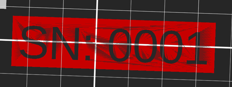
Then I sliced...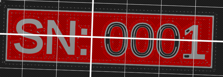
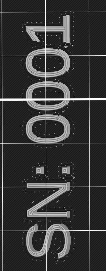
This second picture is just of the first layer. It is adding a gap between the component and the serial number panel, but that gap is only on the first layer. I'm also not sure why it is putting filament into 0's and the 1. Second layer looks as expected.
Now I add in my text. Here are my first and my second layers.
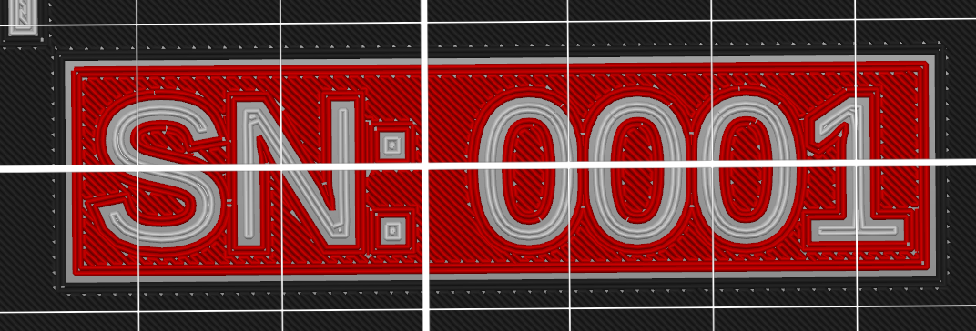
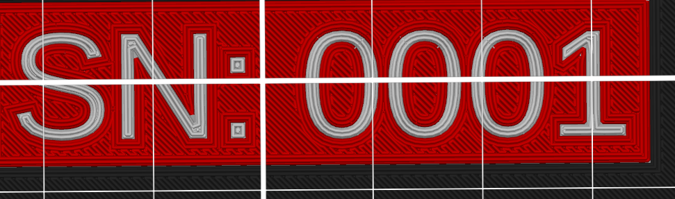
I think this will work. The first layer might have a fine gap around the text, but I think it'll be good enough. I think it'll look better than using a marker too. I can then export two new models (one for the label blank the other for the text) using the same file names. I can then tell PrusaSlicer to reload these two bodies from disk and reslice.

RE: Serializing Printed Parts
Got a workable solution!
I edited my Fusion360 file to place a 15x60x1mm cut where I wanted to print the serial number, x=30mm and y=79.5mm. I exported this file to, "ProjectBoxLid.3mf." Then, in SCAD, I used the following script:
use <fontmetrics.scad>;

text = "SN: 0001";
textWidth = measureText(text);
createBlank = true;

if (createBlank) {
    difference() {
        translate([0, 0, 0]) {
            cube([60, 15, 1], true);
        }

        translate([-textWidth / 2, -5, -.6]) {
            linear_extrude(height = 1.2) text(text);
        }
    }
} else {
    translate([-textWidth / 2, -5, -.5])
        linear_extrude(height = 1) text(text);
}
The SCAD output gives me two files. Basically I get the text "SN: 0001" and the negative of that text. I loaded both of these items into PrusaSlicer as a "part" of the original lid. I could then just enter the X and Y coordinates I wanted and applied the proper rotation. Works perfectly after slicing. No weird gaps!
I then go back to SCAD and regenerate the two serial number files with the text SN: 0002, then put those into the file. If I try to reload from disk, PrusaSlicer crashes, but it should work. I'm running an old beta version because of a known bug in the slicer.
RE: Serializing Printed Parts
A more secure method:
serial="0123";
filename=str("/path_to_prototypes_folder/sn",serial,".3mf");
import(filename);
...
then use whichever method you prefer from above inserting:
text(str("SN: ",serial));
This way it's impossible to mismatch the identity, the run only succeeds if the files match.
Cheerio,