RE: I found serious design error in MMU2 electronics hardware
For an undervolt on the MMU, I would first double-check to be sure that the connections to the power supply are clean and well-seated.
One obvious check is to use a known-accurate voltmeter and make sure that the voltage is indeed correct at the supply end, and that there is no appreciable drop at the MMU end under load.
RE: I found serious design error in MMU2 electronics hardware
I own a multimeter but I'll be honest, my electronics knowledge is very much lacking so I'm not really sure how I would correctly test the voltages.
The power cables were snuggly connected to the mk3 board and I've stripped down and rebuilt the MMU unit several times disconnecting and reconnecting the wiring each time so I'm not convinced it would be an issue with the connections.
The basic procedure is to measure the voltage, from conductor to conductor, both at the source end and at the powered device, under load. Making the physical connections to the meter may be tricky, and sometimes you need to go as far as to temporarily tack-solder short pieces of wire to the circuit board and use EZ-hooks to connect to the meter.
One common error is to assume that the negative/ground is consistent and solid, and therefore connecting to a common ground for the measurements. It's best in an undervolt case to measure the potential difference from conductor to conductor at the supply and at the powered device.
I've seen several cases over the years, for example, where a crimped connector (like those used in the Prusa) introduces enough resistance to cause a significant voltage drop, and even cases where it's severe enough to generate enough heat to melt/scorch the insulation and connectors.
RE:
Last week I was totally unable to get a print started because every time it did the limit check it would do each of the expected moves, move to the correct filament slot and then start flashing under voltage. After a few seconds it tries again and errors out again.
It had done this before but usually turning the entire machine off for a few seconds then back on would fix it but on this particular day it refused to start working.
...
The under voltage (all lights flashing both colours) has gotten progressively worse/more frequent recently leading to the day where I just couldn't get it to work at all. Does the problem discussed in this thread seem like what could be the cause of my issues? or something else
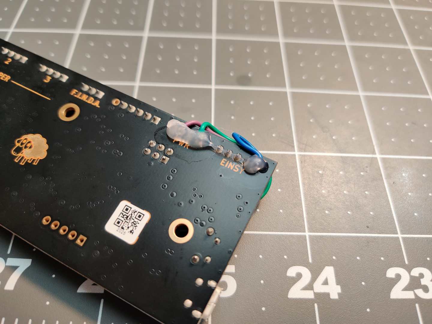
I can't say for certain, but I can say that all of your experiences sound exactly like the same ones I went through. At first all of the suggestions online were that the connection to power wasn't solid enough, and that maybe a loose screw terminal, or a reconnection of power, or cleaning contacts would fix things. For me the problem never went away until I wired in voltage that was 5.2v. I haven't had all lights flash since this change 5 months ago. Earlier posts in this thread show the diode that you can probe to see what the voltage is. Put one side on ground, then the other on one side of the diode, and then the other (keeping the ground side). If it is close to 5v you are fine, but for me it was 4.4v at idle. Because of averaging on the meter, and a lack of Min/Max mode, I couldn't see what it dipped to under load.
RE:
I am SO tempted to either bridge that effing Diode...
...or buy an adjustable buck-inverter to wire in place at the MMU2 to get 5V after the diode...
By the way...
I noted I still have the problem but as long as I keep the cover with the PCB flipped open I'm more or less fine. Maybe heat-buildup contributing or amplifying the problem?
RE: I found serious design error in MMU2 electronics hardware
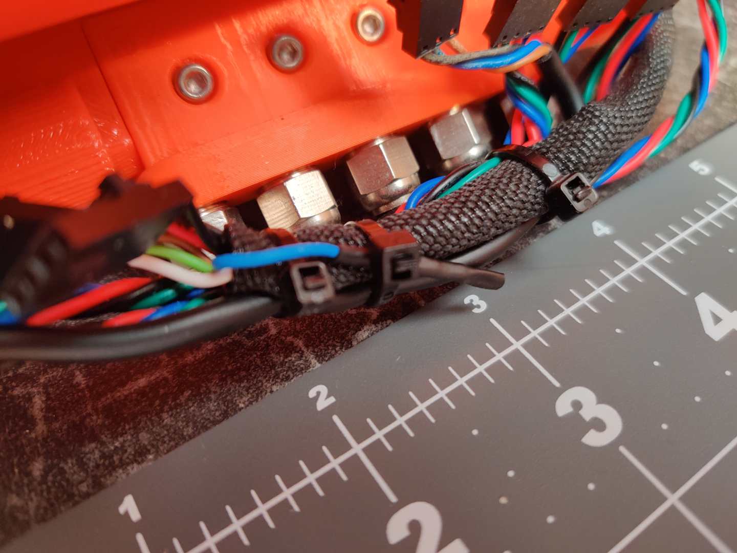
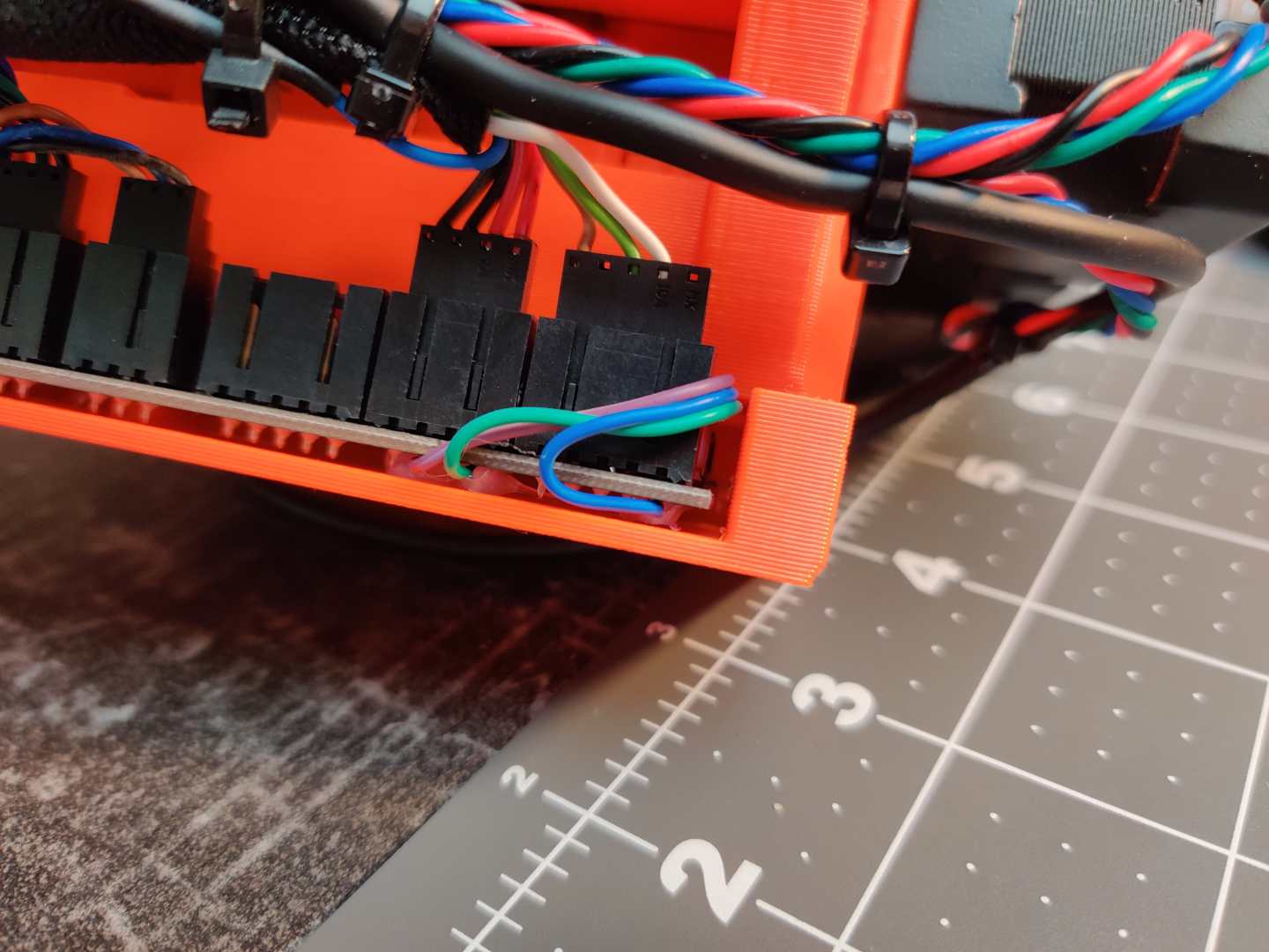
I cant find where I read it, whether it was this post or another, but I have isolated the power wire going to the MMU board with some shielded sleeving and this has been a great fix so far. 
RE: I found serious design error in MMU2 electronics hardware
Bridging the diode will “fix” the low voltage issue, but then if you attach a usb cable to the MMU2S I believe you’ll be shorting the usb 5V supply to the printer’s 5V supply
RE: I found serious design error in MMU2 electronics hardware
I've given it a week or so for my frustration to ease off a bit and I re-fitted the MMU; all the wiring connection have been re-seated, I wire brushed the contacts that connect to the main power outputs etc...
I also had a check over the unit it's self and made sure things like the er... idler? the barrel with all the bearings in, whatever it's called 🙂 was properly aligned and made sure it didn't touch any the idler body at either side (I could always rotate it by hand just fine but I read that if its slightly binding against the side it can cause issues so I tweaked it anyway).
I've done 2 multi colour prints so far and it's working fine for now. But as I said before, I've had it work well for ages and then just start erroring out, so we'll see. If it starts under-voltaging again I'll take some more drastic action such as some of the tweaks mentioned in this thread.
RE: I found serious design error in MMU2 electronics hardware
...given the functionality of how a power-supply works and knowing how it's built...
...why are there poeple that claim that you will "short out" or damage the power-supply...? Where does that 'knowledge' come from...?
...in fact: that's it, I've had enough of that "hear-saying-preaching", I'll bridge that thing at the next opportunity and see how it goes...
RE:
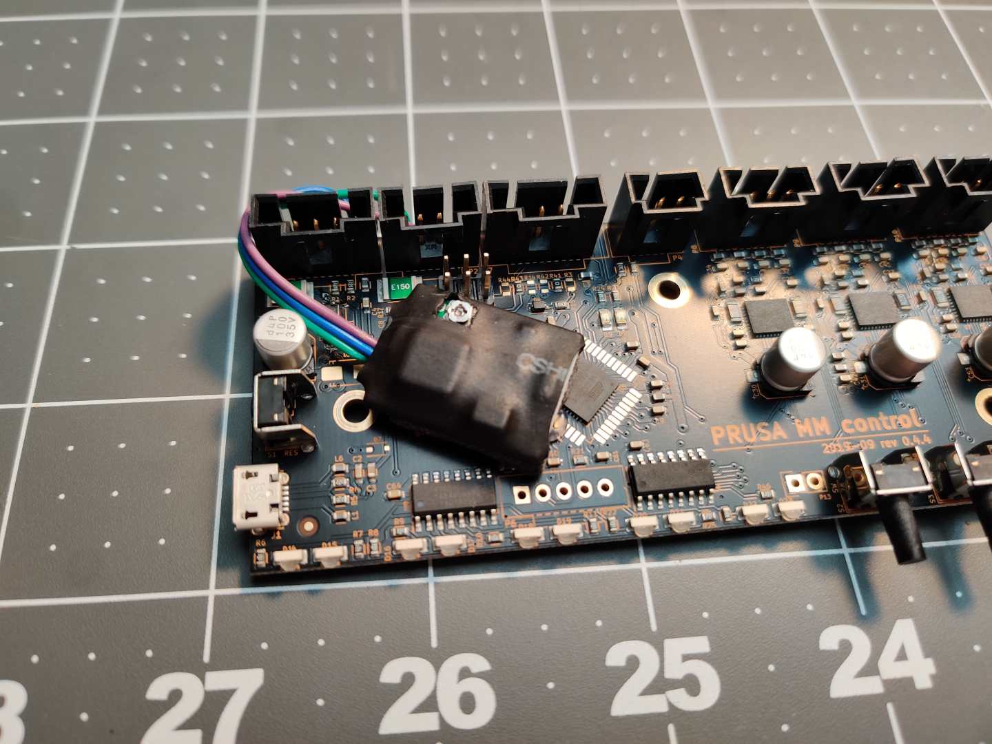
I have managed to fix this by disconnecting the 5V+ from the Einsy, and generating a new 5V+ rail from the 24V+ rail and a mini 24V to 5V adjustable BUC.
I adjusted the output until I got 4.8V after D1.
The intermittent resets, and stalls etc, seem to be entirely gone.
I am taking 24V from the MMU2 board below the 24V connector, and feeding the 5.3V into the data connector from the Einsy where the 5V was normally supplied.
RE:
Well the OP is entirely correct .. the design looks very bad if anything on the MMU diode side needs anything near 5 v.. A silicon diode drops .7v .. that is just its nature.. Sure you can get some germanium that drop less.. maybe a Shottky.. but if you draw any real current, silicon drops .7.. you can’t get around that.. Adding 2 power supplies in parallel is never a good idea. You can get away with it in batteries, but not in electrical power supplies that aren’t current limited. They have a very low output impedance and if one is providing 5.2v and one 4.7v, you have .5v of potential driving zero resistance.. Now in practically will anything blow up.. not likely.. but no electrical designer would ever allow that scenario unless there is something else limiting a failure. Electronic parts have a way of simply weakening and failing over time when stressed this way. Also some supplies look like a dead short when powered off.. So if you power on the USB before the PRUSA, then the USB could be very taxed.. It might not fail immediately, but.. and having to sequence stuff if not ideal.
Disconnecting the diode and adding a power supply on the MMU side to provide power I would think is a good idea, especially powered from the Prusa PSU 24v.. and provide a single good ground so you don’t get any potential drop over the ground wire. The buck supply from the 24v is good.. You want a switching regulator, not a linear regulator (bucks should be a switching types) as you’ll get too much inefficiency from a linear regulator which will generate heat and draw maybe too much from your PSU.. Since people put lights on their Prusa and power from the PSU, the buck should be able to be connected from the PSU since you are only handling the extra current necessary for the buck to do its job.. (without the buck, the 5v comes from the PSU anyway so that current is equal to the buck output), This is really very basic stuff.. and if that diode is a silicon diode (rather than germanium.. and I think it is) you are going to get about a .7 v drop.. The fact that most people have measured 4.2 and the problem is fixed when they add a separate power supply proves that part of the design is faulty. A good engineer designs within specs of all parts.. but parts are pretty tolerant, as I found as a practicing engineer. Even if you treat them out of spec they tend to work.. When things fail often, they are way, way out of spec. This sounds like the latter.
...given the functionality of how a power-supply works and knowing how it's built...
...why are there poeple that claim that you will "short out" or damage the power-supply...? Where does that 'knowledge' come from...?
...in fact: that's it, I've had enough of that "hear-saying-preaching", I'll bridge that thing at the next opportunity and see how it goes...
RE:
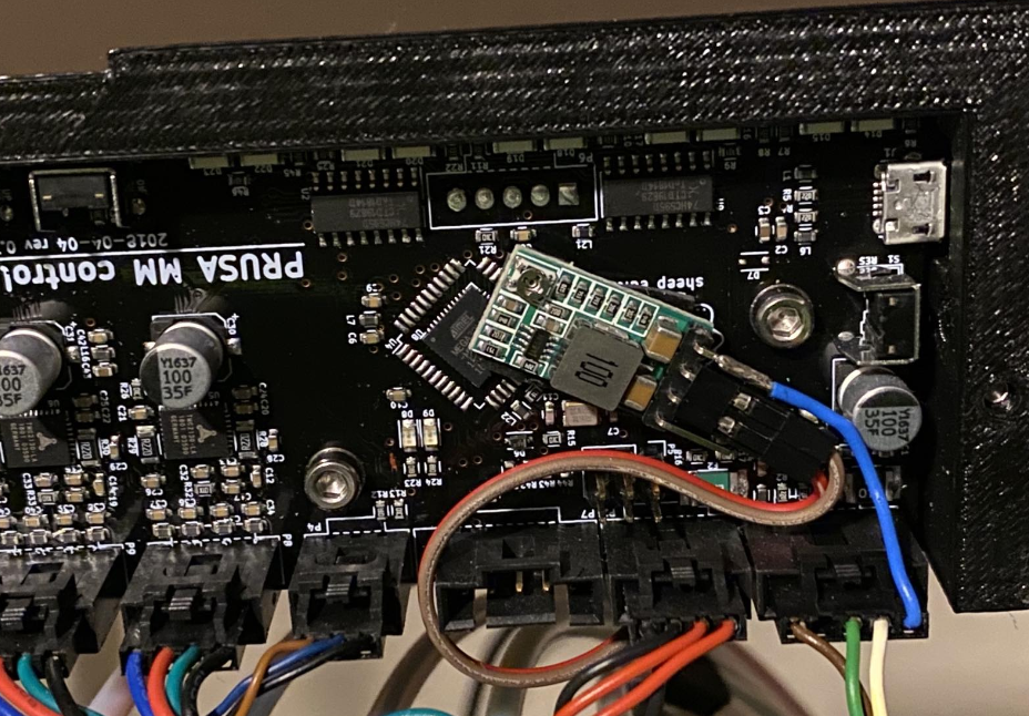
All leds blinking also drove me crazy!!! So I also injected an andjustable step-down disconnecting original +5V from einsy!!! It works!
Thanks guys for inspiration!
RE: I found serious design error in MMU2 electronics hardware
It's great to see some practical examples & pictures how to workaround this issue! What is the type/model of that step-down board ? It seems to be quite a bit smaller in size compared to what I already have.
RE: I found serious design error in MMU2 electronics hardware
I've used something like this (bought locally): MP1584
RE: I found serious design error in MMU2 electronics hardware
Provided the BUC can provide around 3A, it will be sufficient to power the MMU2S board all day long. This are available from Amazon etc for around $6 each. (I got a pkg of 10 for around $15)
You should configure the output voltage BEFORE you connect it to the MMU2S board, or you could quite easily fry the board. I ended up setting the output to 5V then connecting it, and then adjusting the output voltage again to get 4.8V after D1.
This worked so good, that I proceeded to do the same upgrade to all the other MMU2S units.
RE: I found serious design error in MMU2 electronics hardware
Maybe I'm missing something, but I don't understand how plugging in a USB cable from a PC to the MMU2S could damage anything when D1 is shorted.
https://github.com/prusa3d/MM-control-2.0/blob/master/rev.03/MM-control.pdf
- Power comes in on P1 pin 1 (lower left corner of the linked schematic)
- It goes through F1, a resettable fuse. I've seen others report about a 0.2v drop, so I'll assume that is accurate.
- It then goes through D1, a silicon diode. Reports in this thread indicate another roughly 0.4v drop.
- The ATmega32U4 datasheet indicates that 4.5v minimum is required to safely operate at 16MHz. A lot of the reports in this thread are indicating that the measured voltage is around 4.4v, but that's with a multimeter. I'd expect 4.4v to be perfectly fine due to manufacturers keeping a bit of safety margin in their products, but I also recognize that people are using multimeters and not scopes to measure things in this thread. Also, I'd be very very careful in designing something to run outside of its published specs.
- On the top left corner of that schematic is the USB input. The 5v input from that connector goes to the VBUS net, which is then connected through a silicon diode D7.
If one were to short D1 to raise the 5v net on the board, I still don't see any real danger of a USB device back powering the Einsy board. The Einsy board's 5v net should be very close to 5v, and due to D7, the 5v net on the MMU should be notably lower.
Personally, if I were having issues, I'd just short D1. Alternatively, replace D1 with a schottky diode. It looks like the original D1 is silicon diode in an SMA package. With F1 being rated for 150mA, current on the 5v line is likely to be significantly lower than that. But, lets roll with that as the estimated current. This diode is a schottky with an expected voltage drop of 0.25v at 150mA at 25°C. The diode in the design has an expected drop of approximately 0.5v at 150mA.
RE: I found serious design error in MMU2 electronics hardware
THANK YOU HENRY, for backing up my opinion!
Though I did not even check the datasheet. The way powersupplies are built as well as the fact of a voltage-differential between MMU and Einsy was good enough for me to go ahead with the bridging.
I am finally ready to have enought MMU-movements under the belt to say it works: No more flashy-flashy.
While before I could only operate with the pcb-compartment open, now everything is neatly back together and working as advertised...
🙂
...sort of...
...it appears now, that the MMU is fixed, the extruder appears to think it's his turn: set-screw in the filament-gear came loose, so it was no more alligned with the filament path, and while tightening I must've stripped the hex... There's always something... 🙈
RE:
One thing I will agree with is that there are some strange things going on with the power between the main unit and the MMU2S.
When I first installed the switch to power down the MMU, I broke only the red power leads, and for some reason the MMU remained at least partially powered up when that switch was off. Breaking the black ground/common lead as well solved the issue and it's been running that way fine for about two years. I did not feel ambitious enough to find out exactly where the stray power was coming from.
As far as undervoltage, I know from experience that most Arduino type boards can indeed take a joke and will tend to operate normally from something in the range of 4.5-ish volts.
RE: I found serious design error in MMU2 electronics hardware
Well this may have finally happened to me. I came home to a completed print, with the filament still in the tube but not held in the extruder, and all lights blinking on the MMU. The filament did not appear to have any grind marks on it. Pressing the main control knob did resume heating, but pressing buttons on the MMU did nothing to try to make it recover. A quick reset of the printer, and then selecting "Unload filament" on the display, and the MMU properly unloaded the filament without any issue. I suppose I need to bring a soldering iron home from work now. Maybe this would be a good time to print an underslung MMU modification.
RE: I found serious design error in MMU2 electronics hardware
I replaced the D1 diode with the exact one that Henry linked in his recent post. It DID NOT work. I had all lights flashing literally on my first filament load attempt. Shorted the D1 for now and have buck convertors on standby as backup if needed.