An empirical insight into a major flaw of PINDA (v2) bed level probing… and why 7x7 makes things even worse
Hi there,
I admit the headline is quite flashy, but since I started my journey into what’s going on with the bed level measurement, I noticed there seem to be some basic misunderstandings or misconcenceptions within the PINDA compensation method. In this thread I want to guide you through my little research results and what could maybe be done in future firmware adaptions in order to get far more accurate results, regardless of temperature or other influences. I assume this might work all PINDAs including even v1. I’m really keen this possibly enables the brainless “slice and go” we all expect from this great machine 🙂
There is a bunch of data included to think about. I figured out some interpretions for myself, but of course there might be even more in there. So feel free to make your own mind about what’s probably going on there.
TLDR: Current PINDA probing is more of a guessing game right now, measured values are both inconsistent and in many cases incorrect. Automatic temperature compensation calibration gives not only unusable numbers, the compensation method itself of adding/substracting temperature related offsets seems to be unsuited to counteract the (partly immense) drifting of the PINDA values, especially happening at probe temperatures below 45°C. I suggest a new approach to the mesh bed level procedure which relies on an easy validation measurement. Good thing is, PINDA measures pretty reliable and precise within its own set of rules.
Sorry for these harsh but honest words, I try to be as constructive as I can, I promise 😉
Overview:
In this post (part 1), I’ll try to introduce you to the problems I noticed (and might be more or less of a general nature) and talk you through my measurement setup, which simply consists of the MK3S with grey PINDA v2 I have at hand and my Notebook. Furthermore, some basic information on current PINDA probing will be given as far as I understand it (booooring :D)
In Part 2, I’ll present you all my measured data and try to pick you up with my thoughts on each discovery. This contains roughly 4 days of testing, so prepare for lots of plots. I hope you like mysteries!
Part 3 will be about my results and (theoretical) solution to the problem. Unfortunately I’m absolutely not into coding, so the implementation and answer to the question of feasibility I can’t deliver. Additionally, I’ll show you a quick and easy method how you can test if your PINDA shows a similar behaviour - MK3S+ owners with SuperPINDA especially invited with great interest 😉 I hope for some feedback, as this could improve the experience for a lot of us.
There will be probably also a part 3, in which I’ll try to shed some light on the stability of the Nylock mod over time. Too little data yet, but let’s see.
Introduction to the problem:
At my new workplace, there has been a MK3S lying around, which nobody really uses. I asked why, the answer was that it’s simply annoying to supervise/restart every first layer and adjust live Z each time, as well as height inconsistencies for big prints over the whole surface area.
When I started the job, I would consider myself a Newbie with little contact to the topic, but over the weeks I digged quite into it and sucked in all information I could find on filaments, components, mods, heated enclosures, working principles and so on. A bit exhausting, but still fascinating 👍
As I was so nerdy about it, my boss told me that I can take the printer to my home and play around with it.
I disassembled everything and build it from scratch and thought the Nylock mod might be an interesting upgrade to perform. The possibility to flatten the bed could not be that bad, albeit the PINDA following the topography anyway.
After calibrating the printer (Self test, XYZ, belt tension, PID for Hotend/bed, esteps) I set up the first layer calibration with the Prusament PLA that was left over. In order to fine tune the bed, I printed out the suggested pattern for bed level correction and that was the point, where I noticed some first problems. Every print seemed to look a little different in each corner, but mainly some areas were severely too high while others where squished too much. But why, shouldn’t it be the one and only task of PINDA probing to get rid of exactly this? Furthermore, the readings from the Nylock mod
( https://pcboy.github.io/g81_relative/ ) gave varying results each time I checked.
Temp. calibration made things even worse. Is it maybe broken somehow? Is it the fault of the Nylock mod, which actually should have no influence on PINDA probing?
So I researched the topic and found besides some troubled user experiences this interesting thread from stahlfabrik, which got me thinking a little:
If you haven’t read it and you are interested in consistent probing, I recommend it (although I think that they didn’t cover the problem properly, it’s more of a “best you can do” solution). Interesting stuff in there tho.
Testing setup and procedure:
My goal was to get a deeper understanding of how the probing and its compensation works.
For that, I simply hooked up the MK3S to Pronterface and performed some 7x7 MBLs with the G80 command, which can be read with G81. Later on, some comparison runs with 3x3 grid have also been made.
For all measurements, I tried to have as stable conditions as I could achieve, with my room temp being around 20-23°C and no opened windows during each test run.
So I did the following:
Firstly, the bed was heated to 100°C and let sit in for at least half an hour each test, so that expansion has time to settle in and the height can be considered fairly constant. Hotend has never been turned on, because I think the fan could mess things up. Since this is all about PINDA accuracy, it isn’t actually needed.
The PINDA was heated just by being close to the bed and cooled by raising Z. The temperature was observed via the Support menu and noted for every run.
Temp. compensation has been generally turned off in the settings menu for raw values, when it has been turned on for a comparison it will be stated. Magnet comp. was on all the time as it seems useful (but concerning points aren’t used anyway).
In most cases, I started with a cold PINDA measuring at 26-29°C, then proceeded with 35°C, 40°C, 45°C, 50°C and ~55°C. More was not possible with 100°C bed, but enough to get some clue. If I did it again, I’d go up to the full 120°C, but I stuck with it for consistency.
7x7 runs took around 1:10 min each, which meant the PINDA temperature increased with lower temperatures slightly (2-3°C), and dropped off by 2°C @55°C towards the last row. The most stable were the 40°C and 45°C measurements with little to no differences at the end point.
3x3 was much faster at 20 sec and no temperature in- or decrease noticeable.
Little background to inductive sensors and the current compensation method (FW 3.9.3):
-> Can skip if you know that stuff already or it is simply too boring 😛
By no means I am an expert in this regard, but I’ll give it a try. If I am wrong, please don’t hesitate to correct me. This is just sidekick information anyway.
An inductive sensor is basically an oscillator with a coil, where some voltage flows through when measuring. When an metallic object comes close, this coil induces a current into the object which will then build up a magnetic field. This field changes the oscillator output voltage as it gets nearer. A readout circuit supervises this voltage level and switches at a certain threshold. This threshold is a fixed value, so the distance when triggered is based simply on the material properties of the object and PINDA.
General consensus is that PINDAs trigger higher with higher temperature, resulting in lower distance values displayed via the G81 command. Why lower values? The MBL starts always at the home position and moves downwards from there. If it detects the threshold earlier, it has moved less distance from the home position, so the internals think, that home is closer to the zero reference line aka build surface. Consequently, lower distance values mean, that the nozzle is further away at this very position and you’d have to lower your live Z.
In contrast to that, there seem to exist freak PINDAs. Stahlfabrik from the thread linked had to rise its Z value when measuring with higher PINDA temperature, which would mean his PINDA would trigger lower. Might be rare, the involved dev stated he never came across such a probe in his research. Anyways, in order to compensate he needed negative compensation values, which have been enabled since then.
Side question: My below results suggest it’s the higher triggering ones that need these negative values. Does anybody know if they included the sign switch he mentions in his thread? Not very relevant, but confusing tho.
So how does compensation work?
There are 5 temperature based offset values stored in the EEPROM, for each 40°C, 45°C, 50°C, 55°C and 60°C. 35°C is always uncompensated and serves as the reference for each offset. The unit is usteps (1ustep = 2,5µm like 1 click in your live Z adjust). You can think of it as an offset for the triggering height, so positive values will effectively result in a lower measured distance to the zero reference (seen in G81) and a higher nozzle. Negative values will vice versa increase the measured surface distance and bring your nozzle closer to the build plate like live Z would do. A look at the data will clarify it a little more I guess.
If you have now a PINDA v2 with built in thermistor, it will adjust accordingly. Temperatures in between are linearly interpolated, above 60°C extrapolated.
You can look up your stored values with “M861 ?” and also insert your own if you want
( https://help.prusa3d.com/en/article/manual-temperature-calibration_2232 )
Effectively when PINDA temperatures are constant within one MBL procedure, every value gets the same offset. And that’s the part that I think is not addressing the actual problem, as I will show you in the following posts.
Part 2 will be there shortly and I hope I find some time to write down Part 3 as soon as possible.
Maybe some of you are as interested in this as I am. So long
Jay
RE: An empirical insight into a major flaw of PINDA (v2) bed level probing… and why 7x7 makes things even worse
So here is Part 1. Sorry that it takes a while till my posts are published (as I'm new here), didn’t know that the first few posts have to be authorized by a mod.
First of all, a quick overview of all measurements:
Day 1 - auto. calibrated compensation on/off (all 7x7)
Day 2 – Comparison Runs 1-4, manually calibrated compensation on/off (all 7x7)
Day 3 – 7x7 vs 3x3 Run 1
Day 4 – 7x7 vs 3x3 Run 2
Day 5 – Validation runs for the solution, 3x3 Run (both shown in Part 3)
Doesn’t sound like much, but this contains the data of over 140 mesh bed level procedures, as most runs consist of several validation routines. Took a little while 😋
And now, finally some DATA!! 🤓
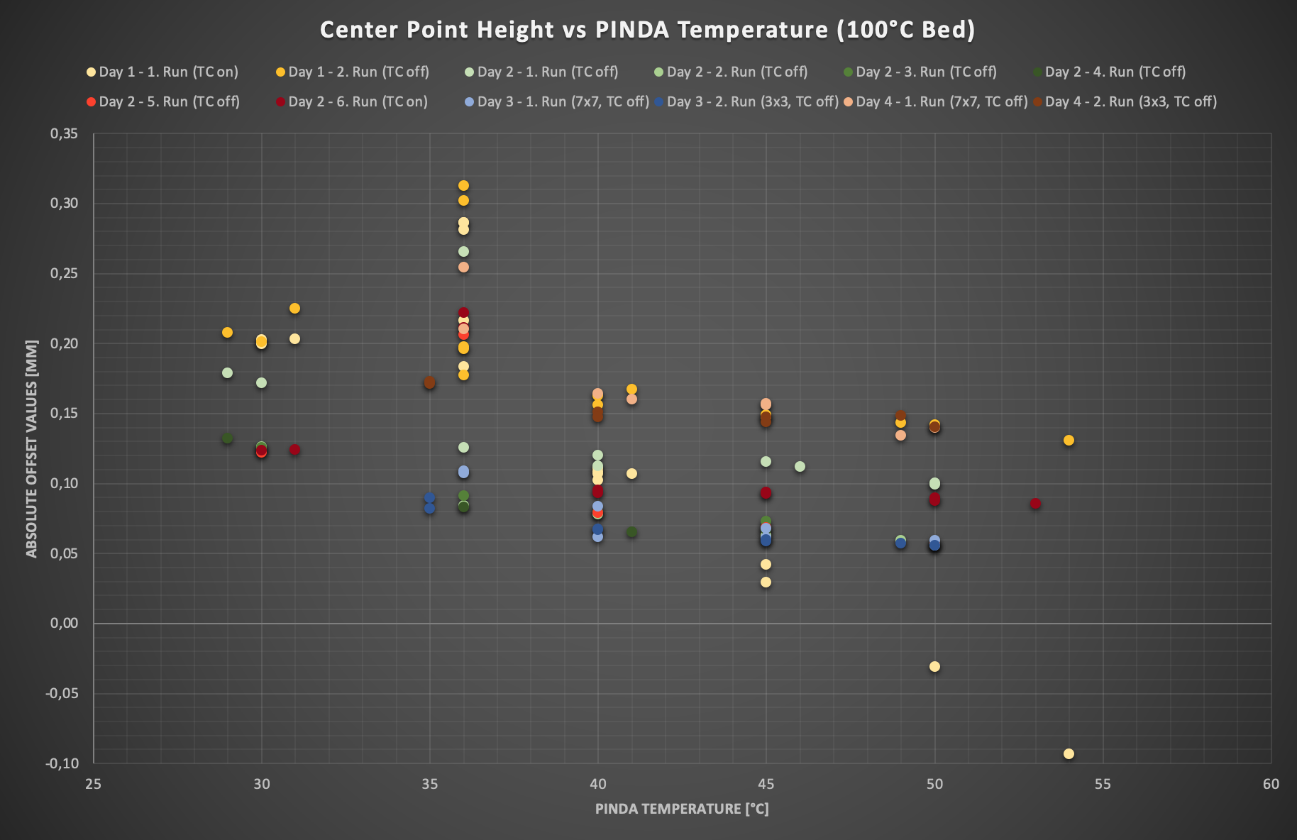
Day 1
I started with 2 runs each for the uncompensated MBL and the compensated one right after (automatic PINDA) temp. calibration. Bed hasn’t cooled down in between. I chose to compare the center height point because why not, let’s have a look what comes out.
For reference, the temperature offsets stored in EEPROM by the automatic “Temp. calibration” were 42,5 µm/40°C, 97,5 µm/45°C, 165 µm/50°C, 237 µm/55°C, 357,5 µm/60°C.
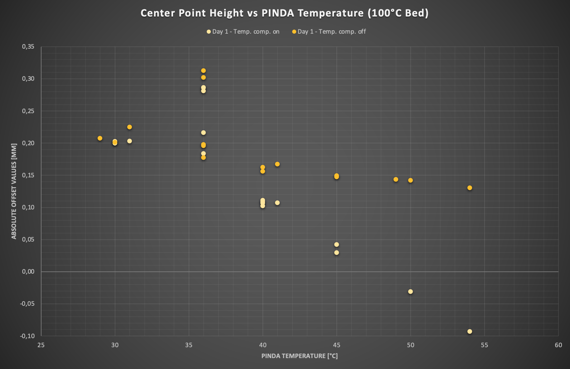
What we first of all see, is that the auto compensation values are far off from helpful, but the offset values seem to match with these in the EEPROM. The goal should rather be to have the same value for each temperature, because with the stable bed and home same position, it physically can be considered constant. The uncompensated run shows only a little drop off, which could be compensated with fairly low negative values. More to that later. What I found convincing was that there seemed to be some repeatability. But there was also this one thing that puzzled me, and I had no clue where it came from. At the 35°C mark, there have been two different “height levels”, which occurred in both comp. and uncomp. runs. Was this some kind of error or what is this? You will see, this was not the last time it happened.
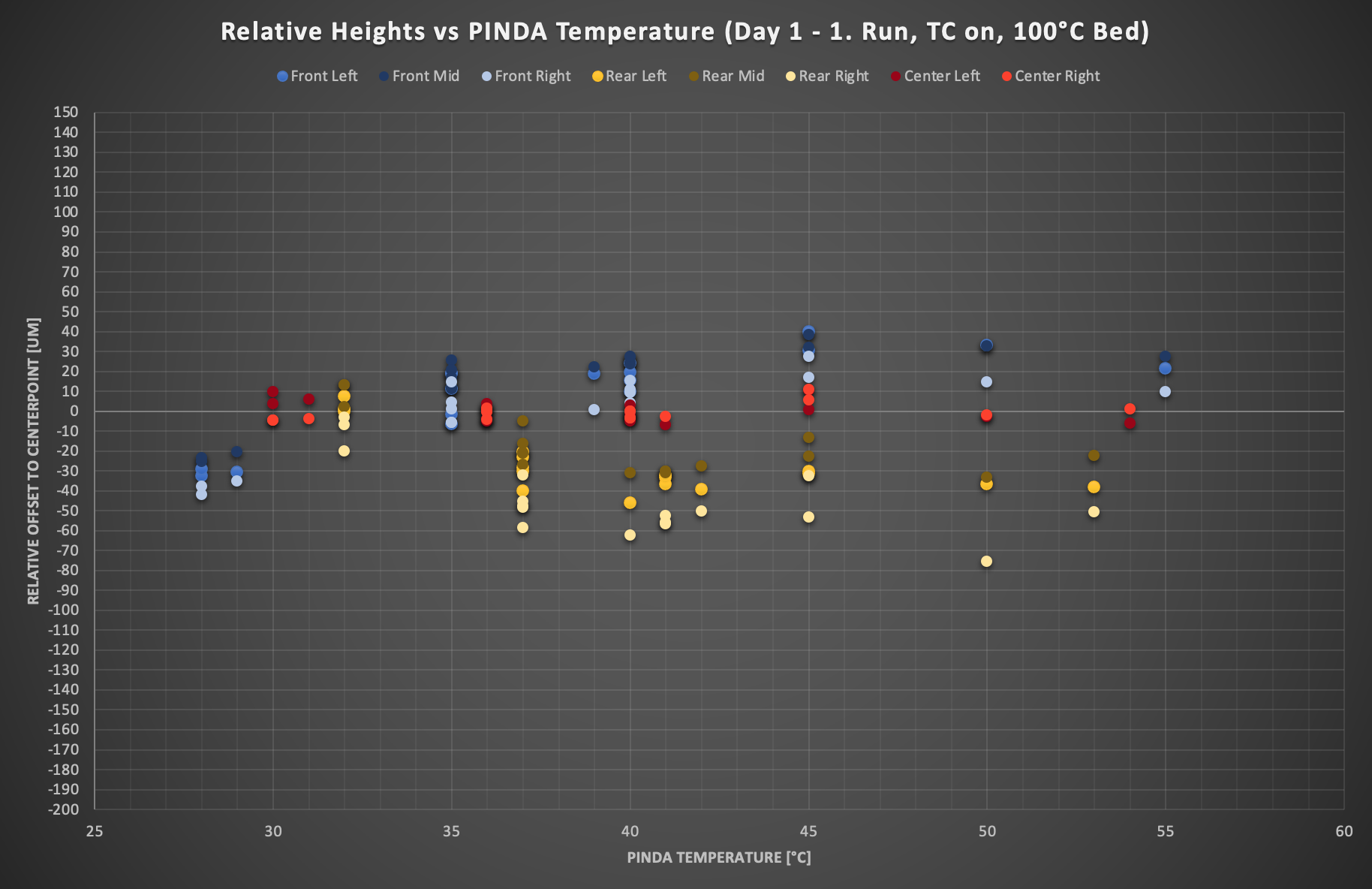
Additionally I made another plot with all the 8 outer bed point heights relative to the center point height (= 0). At first glance this plot might seem a little confusing to read, I suggest to follow each color at a time and draw some imaginary lines between them.
Again, repeatability was good. But why do the values for front and back row drift apart with temperature? Only the center row seems to stay relatively constant. Is it because the last row was measured with 37°C instead of 35° for the front? And which offset is now the correct one? Questions over questions…
For reference, I also post the same plot for the compensated values, but I assure you this is not the right trace to follow. So don’t invest too much energy into it I’d say 😉
Day 2
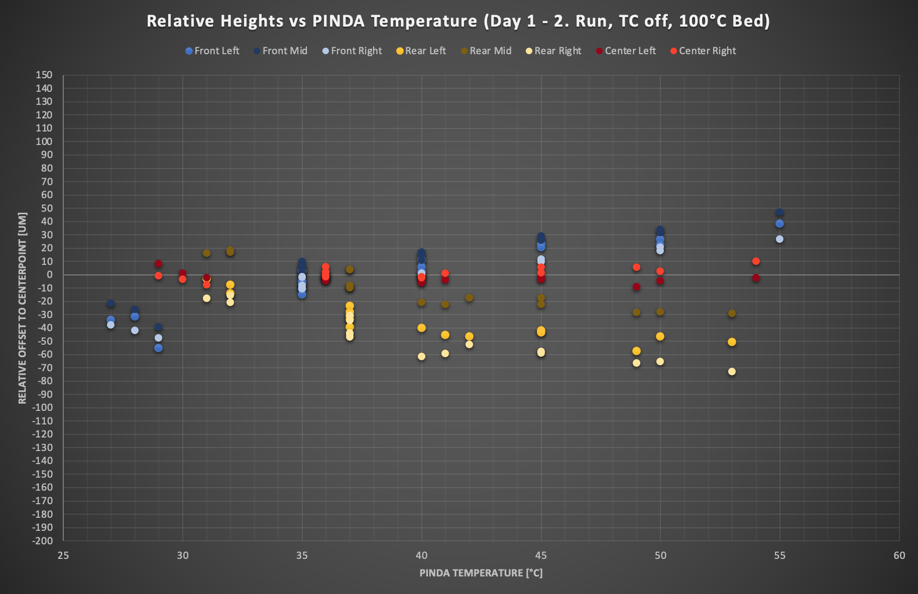
The next day, I repeated the uncompensated run. As you can see, the levels have changed quite a bit, but the temperature related drift is still as present. What a mess...
I let cool down the bed and reheated it to check, if the values are still repeatable.
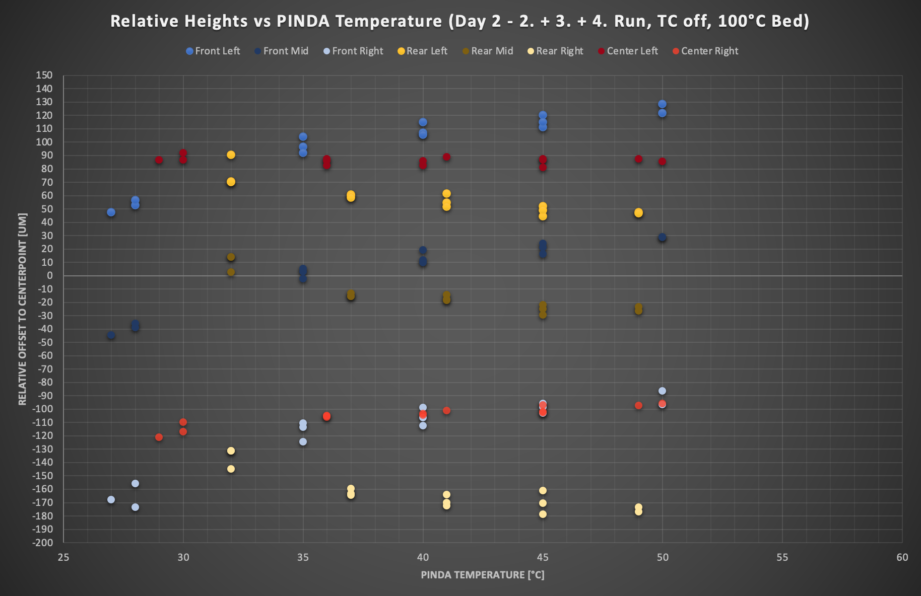
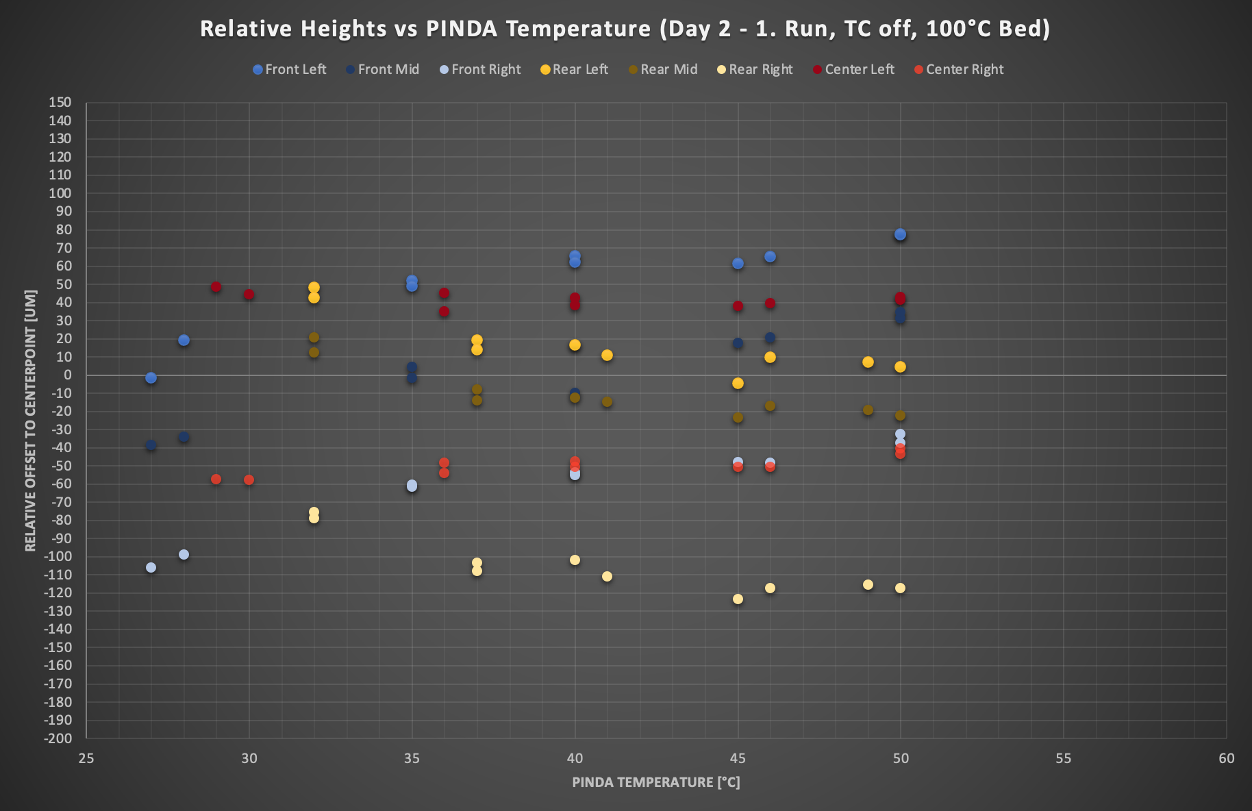
Ooof, the relative points were even more off, but at least constant for each run. Interesstingly, all 3 following runs have produced similar offset values, although I did another cooldown & turnoff run between 2 & 3, a hot turn off/on between 3 & 4 to investigate, if this has any effect on height values. Lastly this temperature drift really seems to be a thing, also the center right has this time a little bit the tendency like the the front row.
Furthermore, I compared the absolute heights of the center points to the previous day.
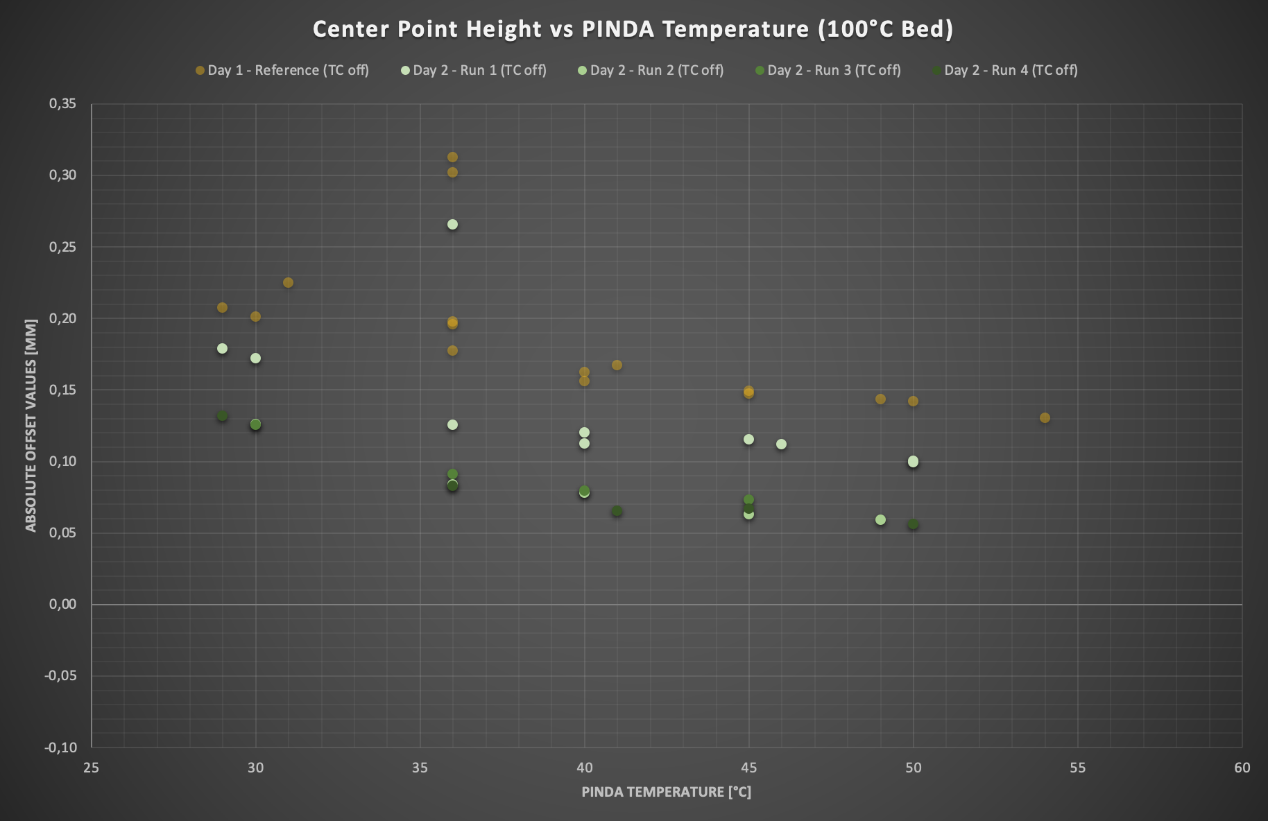
Also quite a bit shifted compared to day 1. And again this outlier with the Day 2 - 1. run, which obviously doesn’t fit in very well. Hmm does not look promising, so many mysteries to unlock.
It was a productive evening and I wanted to also check my custom compensation values, which I estimated from the previous center point heights plots. I came up with values of -15 µm/40°C, -22,5 µm/45°C, -30 µm/50°C, -37,5 µm/55°C, -45 µm/60°C. For comparison I performed an uncompensated run directly before it.
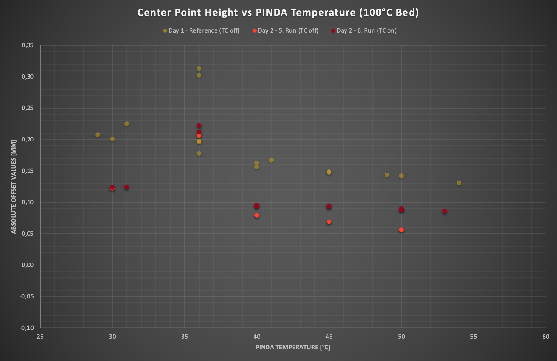
Result goes in the right direction and might be usable, but slightly too less for my liking. Again, the unpleasant 35°C mystery, but no idea whatsoever. So let’s have a look if unexpectedly anything major has changed on the “relative bed point height” side.
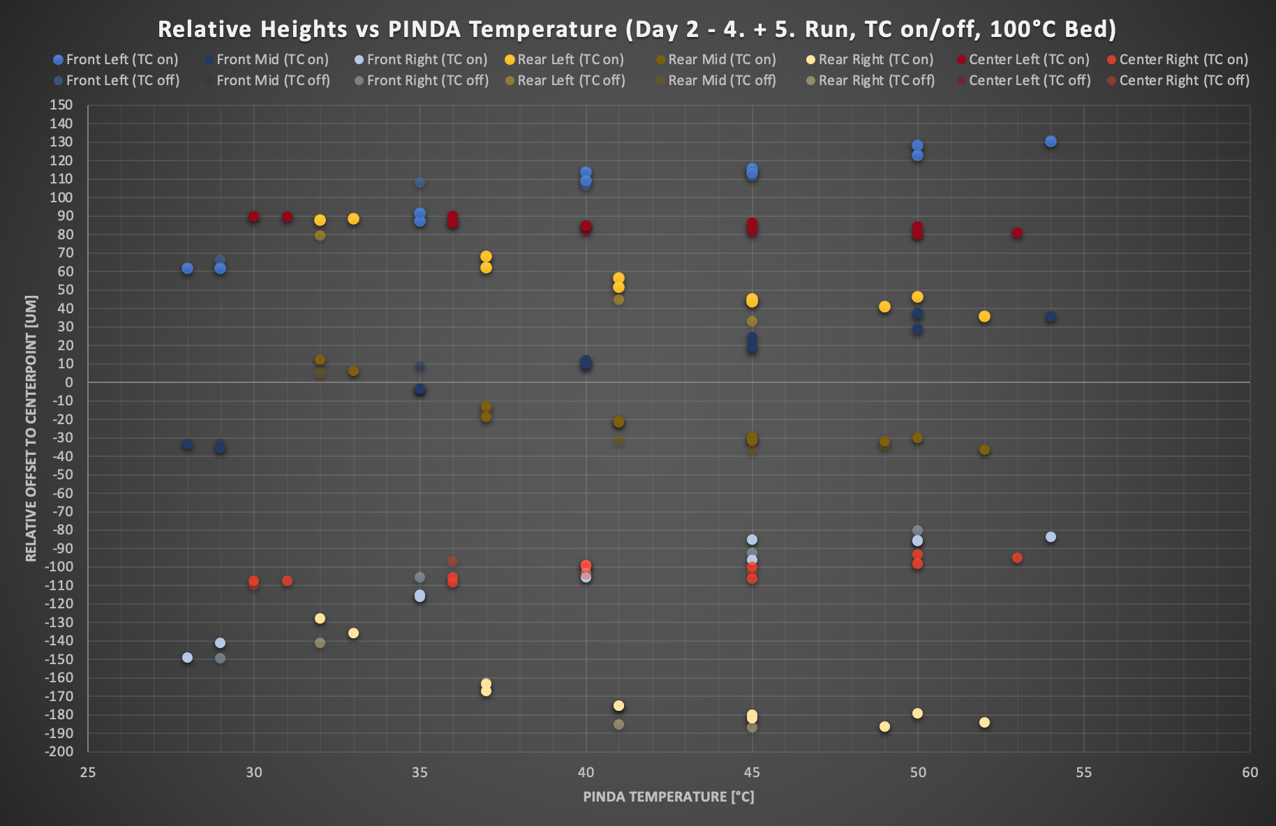
Same ballpark I’d say, no surprises. This leads me slowly to the conclusion that I won’t be able to properly compensate for the height difference of the front and rear that comes with temperature. The only tool there is to compensate for that is the “Bed level correction”, but this again will be only correct for one PINDA temperature range and is far away from the “brainless slice and go” I hoped for. Admittedly, I didn’t even have clue why this gap increases. I thought about this and that as an explanation, but nothing seemed to add up. The minor temperature variations within each run cannot be the only thing, that affects it. And the worst part, I still didn’t know which temperature shows the correct height difference, so how far off are front and back really?
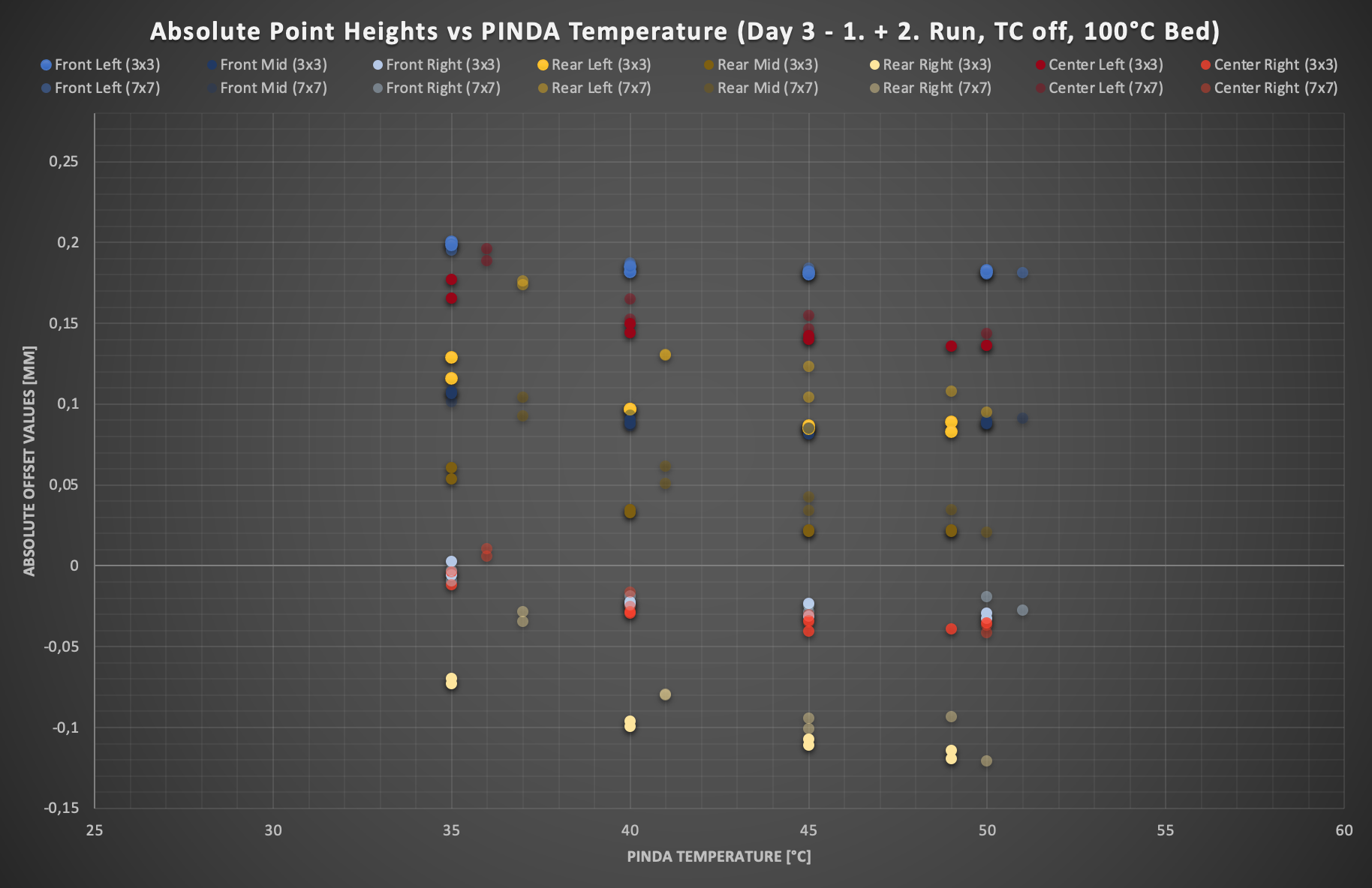
Day 3 & 4
On days 3 and 4, I thought maybe comparing the 7x7 grid with some 3x3 grid measurements will clarify some things, as the latter leaves the temperature in- & decrease nearly out during a run and provides me with some more accurate results.
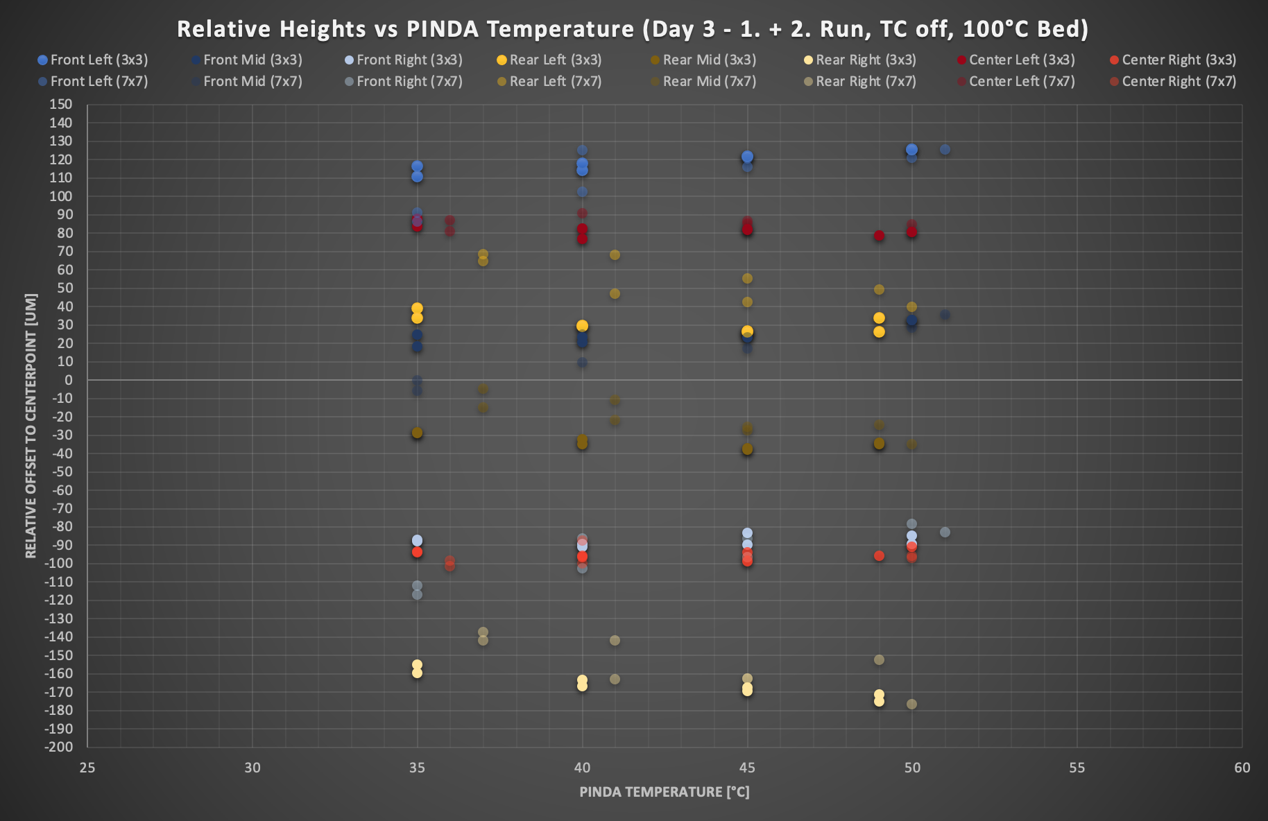
And it did. What we can see here, is that it’s the lower temperature range that is off with the 7x7 grid. Still, there is a slight tendency of spreading towards the higher temp range of the 3x3 runs noticeable, but we are getting closer to steadiness
Yet there’s something strange happening with the 7x7, why are the values higher on the lower temp range? My vague theory was destroyed, that there will be differences due to the PINDA warmup during the 50 sec longer run (as it also ended at 37°C instead of 35°C), but a warmer PINDA would mean lower values instead of higher ones. Again, there must be something else.
Day 4 showed the same behavior, but its little harder to read, because all bed points are again closer together.
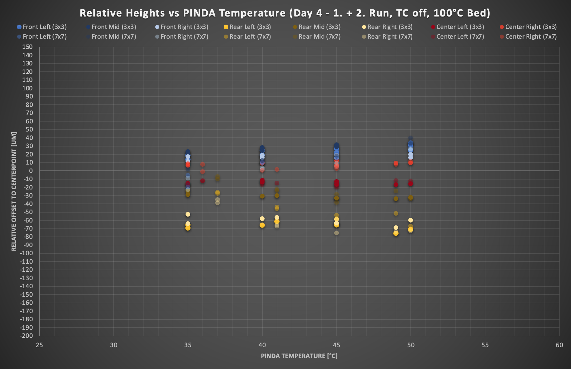
Let’s see what the absolute Center Points look like:
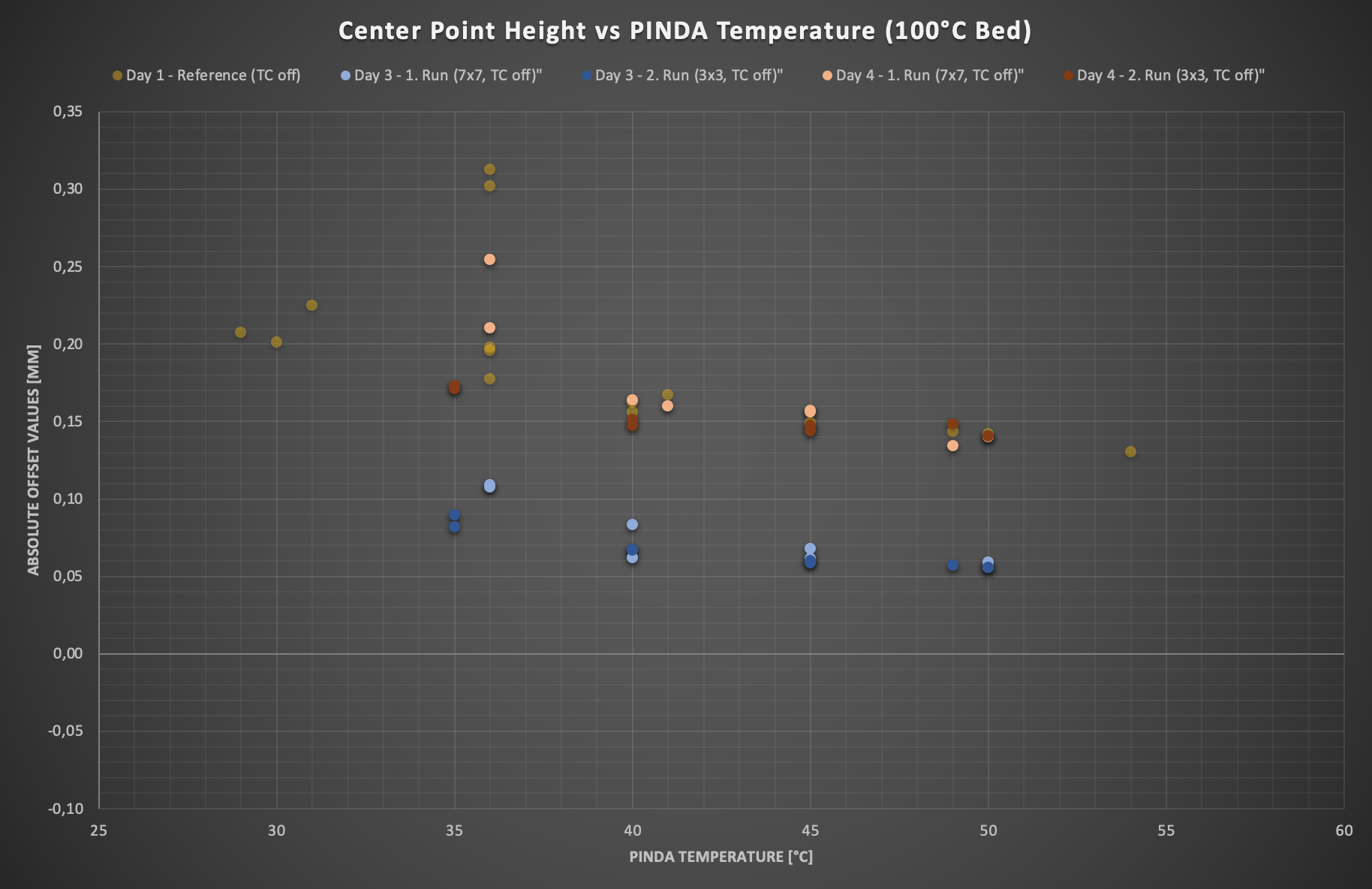
Ok, so on day 3, values are shifted down, on day 4 they are on par with day 1. At 35°C, values are slightly drifting upwards, at higher ranges they fit more or less. This shift is somehow difficult to understand, might be again the unstable Nylock mod, don’t know.
Now what to do with all this mess?
Some unanswered questions remained. What about the 35°C two level phenomenon? And has it maybe something to do with 35°C rise of the backrow? Also why are the centerpoint heights extremely different in height for each day, is it really just the Nylock mod? Time to let all that information sink in and let the subconsciousness do its solving job.
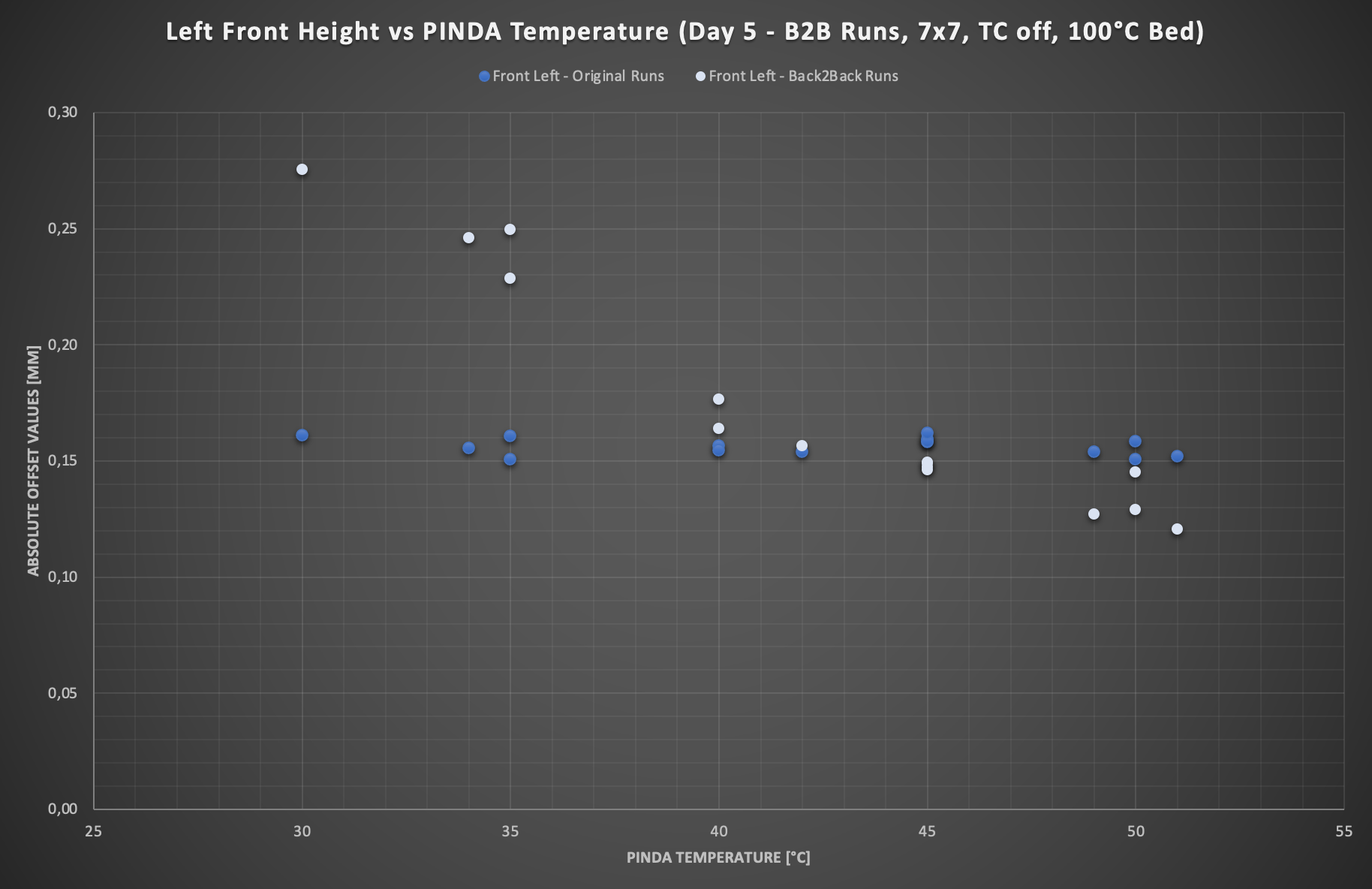
At work, an idea came to my mind where this might heading. I did some short rearrangement of the absolut height data and plotted the front left point (=1. measurement point) instead of the center points.
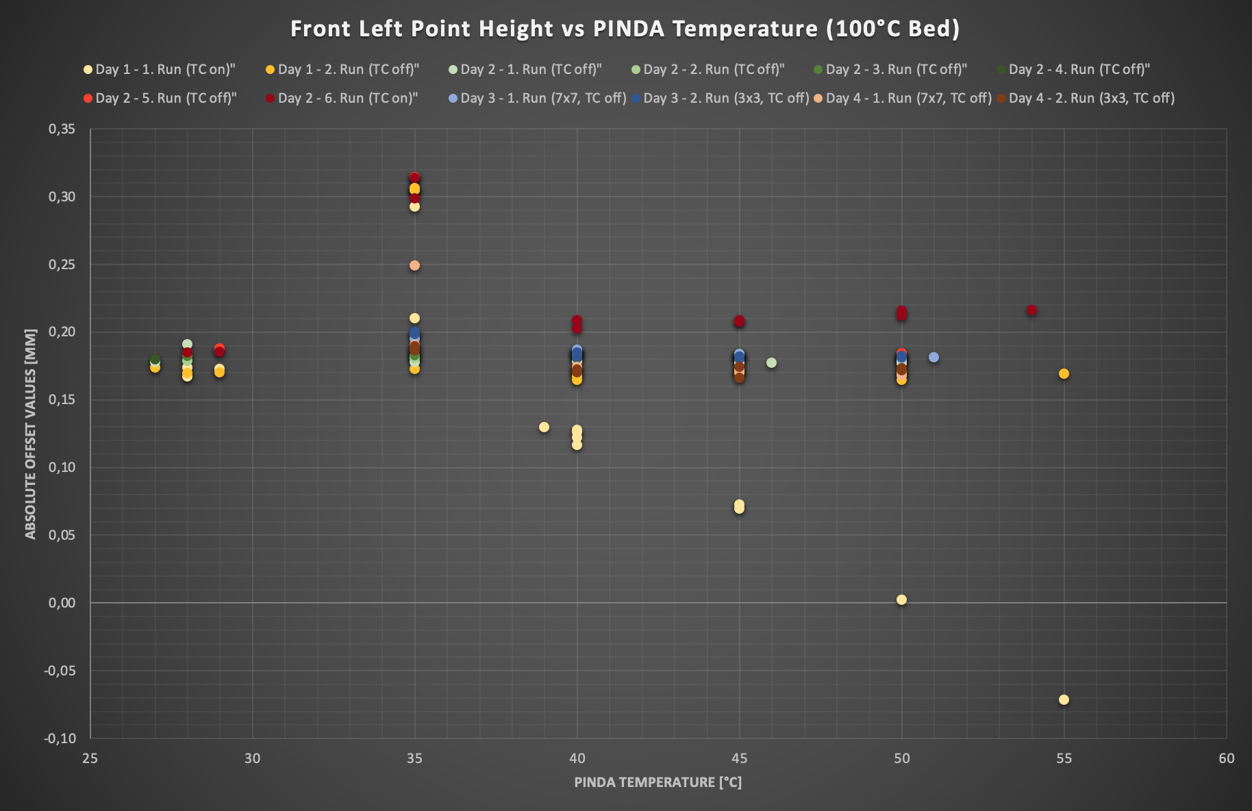
Wow, crazy. Way more than 100 bed levellings across 4 days and all are nearly the same height. Furthermore, with these points the manually entered compensation values (dark red points) are too high, the same which were slightly too low for the center points. Also there is almost no height drop with temperature noticeable.
If we compare that to all center point heights, they are all over the place. Don’t forget, these are from the same measurments. My feeling said, it could not be the whole truth that it’s down to bed deforming due to the Nylock mod. If that would be the case, why only they and not the 1. measurement points in the front?
I also took a second glance at the 3x3 vs 7x7 runs, but this time not relative to the center point, but rather in absolute values.
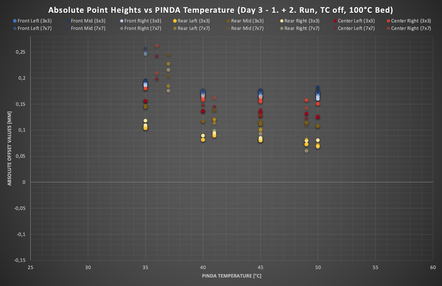
Very interesting. It clicked somehow and I knew what to do next, but I’ll leave it there for now 😋
Maybe you also get the idea how to combine all this stuff. Everything is in there, so enjoy the puzzle fun 😀 If you have any questions, feel free to ask.
I hope Part 3 will be written down soon.
Cheers
Jay
RE: An empirical insight into a major flaw of PINDA (v2) bed level probing… and why 7x7 makes things even worse
Part 3 - Solution time
At first, before heading into details, I want to introduce you the validation measurement consisting of 4 runs à 4 temps. Less confusing stuff, just a plain and simple demonstration of how untrustworthy current probing results are for this MK3S:
Ordernr. 0 is the Front left point, 24 is the Center point and 48 the Rear right point. Just like your printer probes with the 7x7 grid
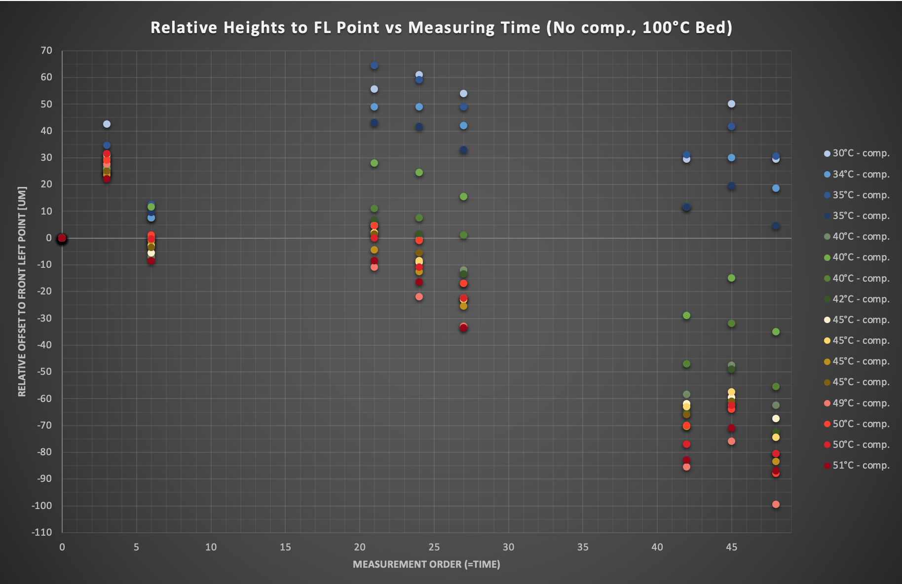
Short interpretation what this result means for the everyday print:
As we have seen, the first point is the most consistent and errorless in the whole range. Now if we take the same print over the whole build plate, the same bed (deformation), live Z adjust, etc. and measure it beforehand, one time with 35°C PINDA and another time with 50°C, PINDA would tell us that back row is 0,07mm above the first point at 35°C and 0,10mm below the same point at 50°C, and this without any changes to the bed. That’s a difference of 0,17mm (!), almost one whole layer if printing at 0,2mm. If you set up your live Z adjust perfectly for the front row, the layer in the back would either be much too squished (35°C) or way too loose (50°C), just because of 15°C different PINDA temperature. Pretty crazy actually. And my guess is, that not few first layer adhesion problems might be somehow related to this without knowing.
For the center it’s of course not that distinct, but a variance of 0,09mm is still bad and will results surely effect layer adhesion at some place of the bed.
But even if it’s not planned to print over the whole bed, this makes life complicated. Let’s assume we want to just print in the center. If measured height changes about these 0,09mm depending on your probe temperature, this would mean you would have to setup your live Z adjust accordingly for each probing temperature (which we actually had to do with the MK3S)
I know there are some workarounds, like establishing routines with a preheated PINDA (which I strongly recommend after the research), bed level correction, adhesives and lastly using the current compensation method for the area you print the most, but it’s no more than countersteering when actually having a flat tire (quote by Tom Sanladerer which I thought is funny 😀)
The Nylock mod doesn’t improve things by the way, as the PINDA would do these mismeasurements there the same way. This is just there for evening the surface of the build plate and subsequently the print.
There might be also less sensitive PINDAs out there and the outcome is not as bad as in this example, but I guess it would still be nice to press just the button and print perfect first layers regardless of the PINDA temperature (and many other factors we do not know), giving you simply the correct values without adjusting, correcting, minding,... anything at all
Well, here is my solution for that (this is the exact same data, only with one little trick added):
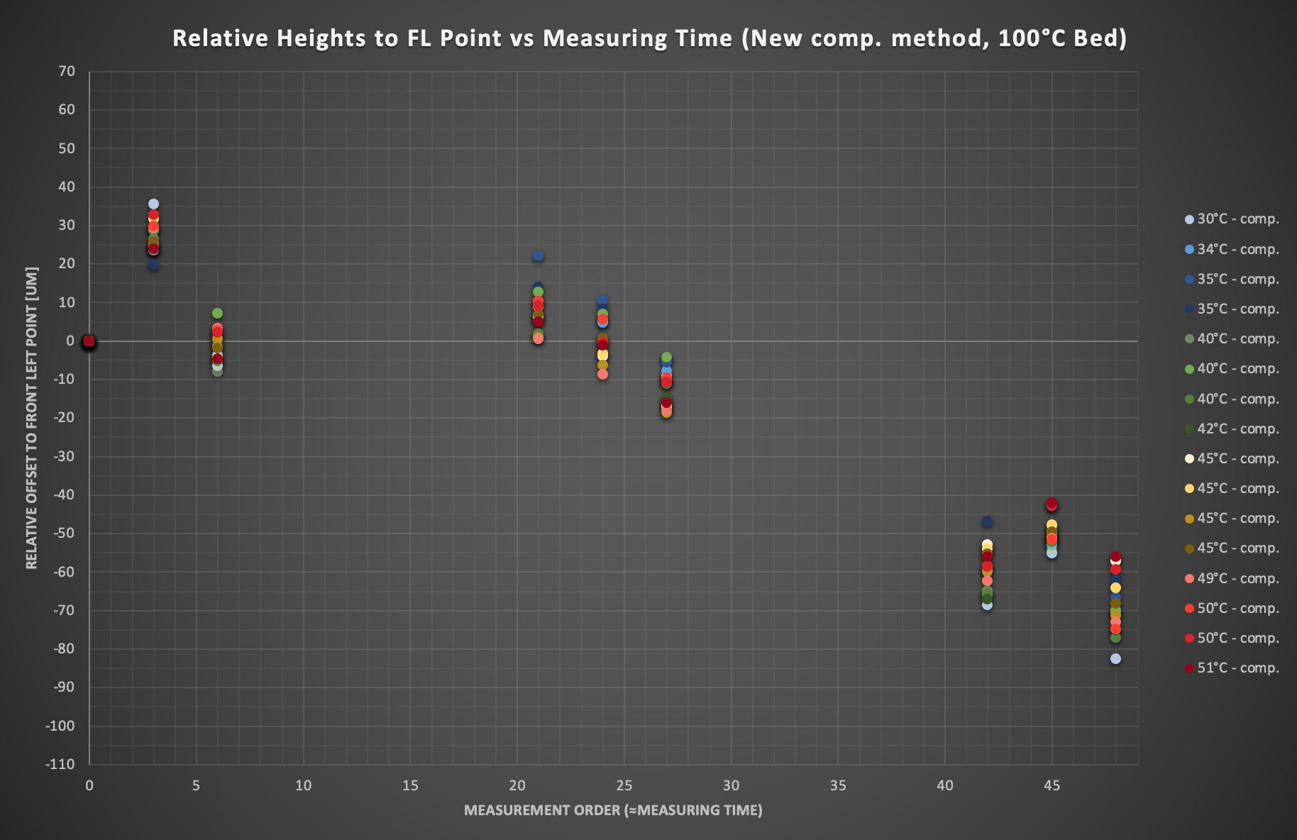
Wow! Finally some reasonable values across the whole range 🙂
The moment I pressed enter for the plot and saw the result, it blew my mind how well it seems to work while it is so simple to do. Without any thermistors, assumptions, look up tables and so on. And the best part: it doesn’t even need any calibration.
All we do is to ask PINDA, how it felt today instead of trying to somehow predict, how it might be feeling 😀
But let’s start with the explanation:
To sum things up, the temperature dependency comes only gradually into effect. The longer PINDA measures, the more it will show. The first point/row is hardly to not at all affected, while the last row will shift in an extreme fashion as we have seen. The center row is therefore only about “halfly” affected. 7x7 runs pronounce this effect of course way more, as the “on time” of the PINDA is more than 3 times as long compared to the 3x3 grid.
Interestingly, it’s the lower temp range which rises too much with on time instead of the values dropping too low with higher temperature.
I have a vague feeling, that we might deal here with several superpositioning effects I will never really understand (temperature, magnetoelectrical stuff, humidity, …), so that pure “on time” rises values while temperature brings it down again or somewhat like that, resulting in almost usable values for the higher temperature range. But that doesn’t matter anyway, as this shouldn’t generally rely on predicting anymore.
If we take a look at the Front Left and Center Point heights plots at the end of Part 2, while the first ones being dead constant, the latter show no real offset pattern to my eyes, at least no pure temperature related one. Sometimes they were lower, sometimes they were little higher and the reason for this might be anything. We simply would never know which height Is the real one.
So why does the current compensation method not work for this kind of problem?
Well, what it can do is to mostly adjust the overall height level of one MBL run, kind of an automatic Live Z adjust if you want to think of it that way. But what Live Z Adjust can’t do, is to lift one corner up, while it lowers another on (at least if the temperature is equal along the run). If we look at the first plot above, it would simply lift or lower the values equally across the bed within each run, as they were measured at (nearly) the same PINDA temperature.
Of course, we could set up huge gradients in the EEPROM that are able to account correctly for small temperature changes, but I think you also can imagine how your overall offset would look like when measuring at 50°C instead of 35°C 😛 Just have to take a look at plot 1 in part 2.
So what it basically fails at is to bring in the crucial time or progressing element. And this is something I tried to integrate as easy as possible.
How does my method work?
The only thing I added to the MBL, was to simply measure the first Front Left point again in a Back2back run immediately after finishing.
That way, I could find out, how much offset was added due to PINDA physics. The first measurement was the only real constant during all testing, with only having this weird bug or phenomenon of sometimes measuring ~0,1mm too high at 35°C sometimes (but this one will very much make sense soon).
So when measuring the Front Left one again, it shows mostly different values than in the consistent first run. As we know, the drifting of the values is happening gradually with measurement progression, ending in the 2..measurement of the Front Left point. The rest is the easiest thing you could imagine, good old rule of three 😋
I assumed, that measuring duration including travel is nearly the same for each probe point and the time from the last point to the 2. Measurement equals roughly 2 measurments.
That meant a “time” of 51 points with an “physics added blackbox offset” being
offset = height_FL,b2b - height_FL,original
It doesn’t simply matter what’s happening inside the blackbox, all we need to know what comes out in the end.
Each point n gets now calculated its value according to is order position, with the Front Left Point not being adjusted and starting at n=0.
height_n,adj = height_n – offset*n/50
The same principle works as well for the 3x3 grid, only with 10 or 11 points and the adjusted formula. Of course, this has the idealization of linearity, which might not be 100% exactly correct for all probes, but it’s definitely in the right ballpark at least.
Is the thermistor now useless?
Yes and no. The benefit of this system is clearly that the relative values between the points are fairly valid, but the absolute height of this set could be lower or higher due to temperature (thinking of the Live Z principle of the current compensation again). As all points get adjusted with reference to the Front Left Point, I’d say this is the one you should check for temperature offset. In my case, this is quite small to almost not existing (10µm at max across the whole range), as we can see at the end of Part 2 and in the absolute height values from this solution run. And maybe you find there some old friend who likes to step up once in a while at the 35°C mark 😉
Turns out, the 35°C bug was probably just a too quickly measured 35°C run after the 27-29°C runs have heated up so quickly and the succession run followed to early. So PINDA had it blackbox still filled 😀
What to do with it now?
If all this is implementable in the firmware, I don’t know. Maybe some of you have a idea about it and likes to play with this approach, would be nice if someone finds this project interesting too and has a bit more clue about coding than I do 🙂 Don’t know if Prusa devs have a look sometimes at this forum, could be also maybe interesting to brainstorm about it.
Further, it would be nice to know if more PINDAs out there behave the same way. SuperPINDAs would also be really cool to see how they perform.
To see yourself how inaccurate your PINDA really measures, I have here a little procedure:
- Hook up Printer to Pronterface/Octoprint if possible
- Seutp 7x7 MBL with 5 probes and temp. compensation off
- Position the Extruder at the top of the printer
- Heat up only the bed to 100°C or so and let it sit in for a few minutes
- Check PINDA temperature in the support menu
- Auto Home with G28 W
- Start G80 when PINDA is still rather cold
- Type in G81 during the run and enter it right after the last point
- Change to G80 as fast as possible and perform another run
- Repeat that G80/G81 Back2back run with hotter PINDA (5min in Auto home position should be enough)
- Browse in history and maybe paste each run to https://pcboy.github.io/g81_relative/
- Write down bottom left value from each run
In my case, I got mostly something like 0,16 -> 0,25 and 0,155 -> 0,13 or similar. This would indicate, that your bed levelling may benefit also a lot from it.
Nevertheless, the new MBL should work nicely in each case, no matter what values.
That’s it for now. Maybe I will take a look at some Nylock data in the near future, as I’m lately able to get some usable values out of the G81 data with this new approach.
Cheers
Jay
RE: An empirical insight into a major flaw of PINDA (v2) bed level probing… and why 7x7 makes things even worse
I hope this gets the attention of Prusa.
I find it curious that your colleagues at work got frustrated with the first layer calibration to the point where they didn't want to use the printer anymore. My experience hasn't been like that. I bought the Prusa i3 MK3S because I wanted to spend more time printing with it than tinkering with it, and I feel it was a good purchase for that purpose.
One question I have: While the printer is warming up to prepare for printing, I like to have the print head raised fairly high up so I can wipe the nozzle clean when it's hot, before the print head starts moving. From your work, I suspect this may be harming my bed leveling calibration because the PINDA probe is far away from the bed during warm-up, and the probe starts warming up while it's doing the calibration. Would it be better to have it down near the bed while it's warming up, so the probe temperature could be somewhat more constant during calibration?
RE: An empirical insight into a major flaw of PINDA (v2) bed level probing… and why 7x7 makes things even worse
@this_dude_jay
You lost me at the measurement method. Is it just the G81?
You imply you are measuring the actual PINDA sense distances as the 7x7 bed level progresses. Please explain the method used to collect these values.
RE: An empirical insight into a major flaw of PINDA (v2) bed level probing… and why 7x7 makes things even worse
As for bed level issues; an easy way for dealing with the thermal instability is just to start the bed level at a known PINDA temperature. A few gcode commands in the startup gcode and done. Here's the segment that does the dirty work.
; cool down PINDA
M106 S255 ; turn on fan
M104 S0 ; turn off nozzle heat
M140 S0 ; turn off bed heat
M860 S35 ; wait until PINDA is less than 35C
M106 S0 ; turn off fan

; preheat nozzle to a low temp, get plastic mushy before driving into the bed with G28
M140 S[first_layer_bed_temperature] ; set bed temp
M109 R175 ; wait for extruder temp
M190 R[first_layer_bed_temperature] ; set & wait for bed temp
G28 W ; home all without mesh bed level

; soak PINDA then level
G0 X50 Y50 Z1 F3000; this is a good PINDA heating position
M860 S37.5 ; wait until PINDA is >= 35C in winter, 37.5C spring/fall, 40C summer
G80 N7 R5; mesh bed leveling
RE: An empirical insight into a major flaw of PINDA (v2) bed level probing… and why 7x7 makes things even worse
Then there's the fact the latest PINDA Prusa is using - the SPINDA - is not nearly as temperature sensitive and no longer has the thermistor to monitor temps. It appears to work quite well without any fuss.
RE: An empirical insight into a major flaw of PINDA (v2) bed level probing… and why 7x7 makes things even worse
@tim-2
It does work well. No doubt about it. I am slowly converting all of my printers to the SPINDA.
--------------------
Chuck H
3D Printer Review Blog
RE: An empirical insight into a major flaw of PINDA (v2) bed level probing… and why 7x7 makes things even worse
@this_dude_jay
It is amazing to me that some have this problem and others do not. Is it filament dependent or is it environment dependent?
--------------------
Chuck H
3D Printer Review Blog
RE: An empirical insight into a major flaw of PINDA (v2) bed level probing… and why 7x7 makes things even worse
It is amazing to me that some have this problem and others do not. Is it filament dependent or is it environment dependent?
It may be a bit of both. Those of us who mostly use PLA may not see issues as much as people who use higher temperature materials. I imagine environment may also be a factor; in a cold environment it would take longer for the probe to ramp up to a comfortable temperature for good measurements.
Or maybe some of us don't know what we have. How can I tell if my probe is a PINDA or a SPINDA? I bought my printer in late 2019.
RE: An empirical insight into a major flaw of PINDA (v2) bed level probing… and why 7x7 makes things even worse
@anachronist
If you did not update in 2021, you have a Pinda and a sPinda.
--------------------
Chuck H
3D Printer Review Blog
RE: An empirical insight into a major flaw of PINDA (v2) bed level probing… and why 7x7 makes things even worse
@anachronist
Also, the new sPINDA has a black tip and the old one, from Prusa, is grey.
--------------------
Chuck H
3D Printer Review Blog
RE: An empirical insight into a major flaw of PINDA (v2) bed level probing… and why 7x7 makes things even worse
@cwbullet - thanks. Mine has a gray tip. It must be the older PINDA then. I didn't update any hardware in 2021 except for a new heat break because I stripped the threads of my original one. As long as I'm not seeing issues with bed leveling (except for the double tap I mentioned in another thread that arose only recently), I'm not inclined to replace what's already working fine.
RE: An empirical insight into a major flaw of PINDA (v2) bed level probing… and why 7x7 makes things even worse
@anachronist
I would not. I am updating mine as I repair or do routine maintenance.
--------------------
Chuck H
3D Printer Review Blog
RE: An empirical insight into a major flaw of PINDA (v2) bed level probing… and why 7x7 makes things even worse
The issue is thermal stability (or lack thereof) in the PINDA as the OP suggested. It heats up, the sense distance changes. Printing with higher temps heats the PINDA more. You end up with a sensitivity change - one that is especially bad print to print. A 5c change is nominal - and you can usually get away with the differences incurred with warming during bed level. But a 15c change typical after a print will really mess with layer one.
So yeah - the issue is insignificant if you print once a day. It will show up and haunt you more if you print at higher temps or print successive runs.
There's probably a way to cal the firmware based temperatures. The built in cal is a waste of time (see github comments). The G81 values the OP suggests using seem like an option - but are prone to complications since the firmware normalizes the results each run (ime).
I'd use actual layer one coupons to make measurements; or, just buy the new SPINDA Prusa is selling and remove thermals from the equation entirely.
RE: An empirical insight into a major flaw of PINDA (v2) bed level probing… and why 7x7 makes things even worse
RE: An empirical insight into a major flaw of PINDA (v2) bed level probing… and why 7x7 makes things even worse
So yeah - the issue is insignificant if you print once a day. It will show up and haunt you more if you print at higher temps or print successive runs.
Then maybe I never need worry. I sometimes print multiple times per day, but when I do, I always let the bed cool down to nearly room temperature (it takes at least 20 minutes) before I remove the part and start another print. That way I don't have to remove the steel sheet -- the part detaches itself as it cools. So my printer starts cold at each print run, even if I print several things in one day. It is likely that the PINDA also cools off during that time, so the probe is never hot during a bed-leveling calibration.
The OP's printer apparently was problematic even when starting cold.
RE: An empirical insight into a major flaw of PINDA (v2) bed level probing… and why 7x7 makes things even worse
And the title about 7x7 making matters worse is a red herring. 7x7 improves things immensely, and for reasons not covered by this thread.
RE: An empirical insight into a major flaw of PINDA (v2) bed level probing… and why 7x7 makes things even worse
@tim-2 - what I understood from the OP's long report is that 7x7 gives the probe too much opportunity to warm up during the calibration. He suggested a simple correction of measuring the first point again after the 49th point is complete, and the difference between the two measurements of the first point is interpolated over all the other ones to correct for the ramp drift.
RE: An empirical insight into a major flaw of PINDA (v2) bed level probing… and why 7x7 makes things even worse
I agree with Tim. This one of those moments where you do it over and over again arguing it one thing when it ends up being something entirely different.
--------------------
Chuck H
3D Printer Review Blog