Just assembled and calibration prints have problems
My MK3S+ just arrived Monday and I spent a lot of the night Monday and most of the day Tuesday assembling it and starting to calibrate and test it. I have one other 3D printer that, even though I've had a lot of advice about, just cannot get it to print. (It's an Ender 3 Pro.) I was quite impressed with the instructions from Prusa and, other than the time it took, found the kit enjoyable and fairly easy to assemble.
I started it up, fully expecting, even though I had triple-checked all wiring, for it to just die on me, but it didn't. Everything went fine until it came time to do the calibration zig-zag print. The first one had problems and I adjusted the bed height (or is it the offset distance?). My understanding is that when I changed the the number on the display (which only goes down, not up), that it's the height of the bed. The farther away the number goes from 0, the worse the print gets.
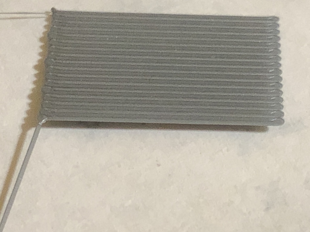
This was at -0.025 (the very first part wasn't - I was still adjusting it):
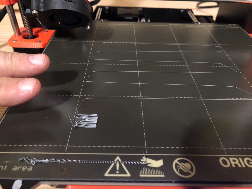
Again, the farther I go from 0, the worse it gets. I tried at -0.500 and it looked even worse.
Maybe I have it wrong - maybe if I get to something like -1 or -2, it'll look better?
Since it got worse as I went farther from 0, and since the handbook says if you go too far from 0, you need to move the SuperPINDA up, I experimented by moving it down and it didn't help. (Made me think it detected that it was closer and adjusted for it.)
So I have 2 questions, but any info that could help me is greatly appreciated!
1) What exactly is the number on the LCD expressing? As it gets lower (as in from -0.005 to -0.010 - just clarifying since it's a negative), is the distance between the head and the print bed increasing or decreasing?
2) Should I just be pushing through this and going to even higher numbers? It was so bad at -0.500 that I felt it was clear the farther I got from 0, the worse it was getting. Is that wrong?
RE: Just assembled and calibration prints have problems
The number represents the height of the nozzle (or the PINDA) above the bed. Your Z axis zero is actually some slight distance above the bed surface, so the more negative the number gets, the closer you are to the bed. The number itself doesn't actually mean anything, it's a function of how the probe is adjusted and the height above the bed.
When I assembled my Prusa, I used the zip tie method given in the instructions to set the height of the PINDA. Haven't had to mess with it since. That seemed to be an imprecise way of doing things, so when I built the Bear I printed a tool that a user here had posted, and used that instead. Printer wouldn't pass cal, said the PINDA was too high. I did some searching on here and found a post giving what was supposed to be the actual measurement, and I used a feeler gauge to adjust to the middle of that range (sorry I don't remember the number). I probably would have been better off just using the zip tie in the first place again.
Your calibration print looks like you need to come way down, i.e. more negative. When it starts making square corners on the zig zag, you know you are getting closer.
RE: Just assembled and calibration prints have problems
Your calibration print looks like you need to come way down, i.e. more negative. When it starts making square corners on the zig zag, you know you are getting closer.
I figured the corners were a major indication something was wrong. So what you're saying is that when I went to -0.005 and had problems, and moved, eventually, to -0.500, that I needed to just keep going? I can do that and test it tomorrow. It just seemed to me when I went to -0.500 that it looked worse, but I agree that it's clear that the head needs to be closer to the bed, so if that's what brings it closer, I'm eager to see if it works. I'll start it out much closer, like -0.750 and go from there.
Thank you!
RE:
For the initial setup, follow Josef´s instructions on youtube:
Once you have completed the initial first layer test, and however crappy the result is (like the crappy result in your original post), move directly to Jeff Jordan´s calibration method at https://forum.prusa3d.com/forum/original-prusa-i3-mk3s-mk3-assembly-and-first-prints-troubleshooting/life-adjust-z-my-way/
Reading the first one or two pages should suffice.
Our moderator Joan has repeatedly replaced the files attached to Jeff´s original post #1 in the long thread of posts; use one of these files or simply construct yourself a square of 70 x 70 x 0.2mm and slice it with your favourite slicer settings. Start printing the file, go to the main menu, chose "Live adjust Z" and move the nozzle as long until you arrive at a decent result, as described in Jeff´s thread. The large-size square will give you ample time and room for try & error.
Regards
Chris
I try to give answers to the best of my ability, but I am not a 3D printing pro by any means, and anything you do you do at your own risk. BTW: I have no food for…
RE:
FWIW my current Z offset on my 3S+ is -1.730. Don't use that as a guide since your number is going to be different than mine (particularly since it looks like you are using the smooth sheet); I just mention it for reference.
This is what I am using to fine tune the offset:
https://www.printables.com/model/105404-live-zfirst-layer-calibration-strip
RE:
The photo the OP posted almost certainly shows the nozzle too high.
I would suggest lowering it quite a bit. -500 is nothing. Values of -1500 to -1800 are common, depending on how the Pinda is set.
If this were mine, I would start at maybe -800 or something and go downward from there, first tuning for the best square corners on the zig-zag and then for the best looking strokes and bottom of the square piece.
After that I would suggest using one of those 3x3 calibration prints and checking to see if further left/right and/or front/rear tweaks are needed.
RE:
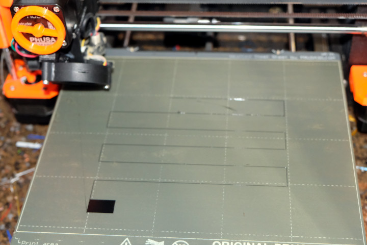
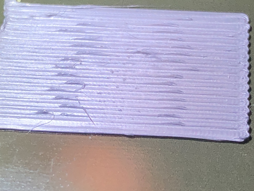
I had limited time today and I adjusted the SUPERpinda and did an XYZ recalibrate then started printing. I tried to get a close up of the square at the end of the zig zag. I think I'm getting closer. It was flat on the bottom, but not as flat on top. At least when I pulled it off the bed, it came off in one piece, which hasn't happened before. It'll probably be late Thursday or Friday before I can do any more testing. These pictures are of the top surface of the square. It looks flat until you look close up.
I still want to try other recommended test patterns and review the thread linked to above - this is just what I had time to do today.
RE: Just assembled and calibration prints have problems
It will be flatter on the bottom due to the flat surface of the build plate.
Are the corners of the zig-zag now square with no pulling of the extruded bead?
How does the profile of the bead look (may need to use magnification) on those zig-zag lines?
RE: Just assembled and calibration prints have problems
It will be flatter on the bottom due to the flat surface of the build plate.
I figured that, but now it is nowhere near a flat surface on top - definitely ribbed and bumpy, but better than it was.
Are the corners of the zig-zag now square with no pulling of the extruded bead?
They're square. I did have some extra stray filaments around. I think that may be because I didn't clean the nozzle well before printing.
How does the profile of the bead look (may need to use magnification) on those zig-zag lines?
It's really hard to tell because they're so thing. Sorry, it was late, so I wasn't thinking of all the points I wanted to include in the post. The square makes me think the distance is too big, but the single lines are so flat and thin (to the point where I can't really see the profile of it) that it made me think the distance was too small.
I notice that first line it does, the short one along the front, before it does the zig-zag, always seems to turn out differently. When the distance was way too far, it was a tiny zig-zag, but it seemed to me the head was not zig-zagging at all. With the head closer, like it is now, it comes out more as a solid line and definitely wider and a little thicker than the zig-zag line.
RE: Just assembled and calibration prints have problems
The basic rule of thumb on the bead is that if the profile is round, the Z is set too high. If it's mostly flat, it's too low. If it's oval or elliptical, that's the sweet spot.
RE: Just assembled and calibration prints have problems
The basic rule of thumb on the bead is that if the profile is round, the Z is set too high. If it's mostly flat, it's too low. If it's oval or elliptical, that's the sweet spot.
I'll have to use a magnifying glass or my jeweler's loupe to look at that. Maybe it's just that I'm not in my 30s or 40s anymore, but it's so thin I couldn't see what kind of profile it has.
After looking at the the recommended thread I'm thinking that a good file to use to adjust the print head distance would be something with a number of squares on it that allows for adjusting the distance while it's printing. (From what I've read so far, the included g-code everyone is talking about seems to be just 2 squares.) It's hard to see a square the size of the one on the test pattern while it's printing.
RE: Just assembled and calibration prints have problems
Actually, on my desk in the home office I have a spare 50mm m42 normal lens that I use as a loupe, and I have used it to view the Z calibration beads.
RE: Just assembled and calibration prints have problems
The information given in the instructions and the forum threads can be confusing. You are getting closer and moving in the right direction. It is worth the effort as once you get the first layer sticking to the bed the prints go much better.
There is a test pattern that someone created and posted that prints a 75 mm x 75 mm(?) square in the middle of the bed. It provides enough time for you top adjust the z axis in real time and look for the best compression of the the bead. It begins in one corner and fills the first layer, for almost 5 minutes. You have a good deal of time to adjust. The provided calibration pattern is good for major dialing in, not fine adjustments.
Also, using a magnifying glass to monitor the print is a great idea. I use harbor freight magnifying headsets and a flashlight to monitor the 75 x 75 printing and adjust the live z axis as it works its way across the pattern. It took me about 4 patterns to dial in my PETG setting. A good pattern will peel off the plate and the strings will not separate when the corners are stretched perpendicular to the print direction. Not at all. I'll adjust the height by .050 - e.g. -1.650 to 1.700. Look at the smoothness of the layer. If your too far away, e.g. -1.100, you will get a lot of ridges in your layer and gaps at the turn around points. If you are to close, i.e. - 1.900, you will get squishing of media at the turn around points, as well as the middles. So you are tweaking the height until all those balance out.
As I said, it took me four 75x75 patterns to dial in my PETG on textured plate. During each plate I would start with my best guess and part way (1/4?) through adjust it some ( up or down). Let it go for 1/4 plate and decide if it is better than the previous section. If better, try a bit more ( up or down .050). Better or worse? Once you get the .050 dialied in, go for .005. Until you really cannot tell the difference. That's as good as it gets.
Write down that number! It dependent on the material (PETG, PLA, etc.) and the plate (smooth, textured). PRUSA has ways of recording the plate's Z value in the printer. Which is beyond this post.
The bigger print sample helped a great deal!
RE: Just assembled and calibration prints have problems
Actually, I find very little difference between the first layer performance of PLA, ABS, and PETg once the Z is dialed in, usually with PLA. Ditto little if any difference between brands of filament.
This last week I have been going back and forth between PLA and ABS and both are printing just fine with no Z adjustment.
I have three Z values stored in the machine, Smooth1 which is the stock build plate, Smooth2, which is the re-skinned smooth plate but is essentially the same as the factory, and Texture, which is the Prusa textured plate.
RE: Just assembled and calibration prints have problems
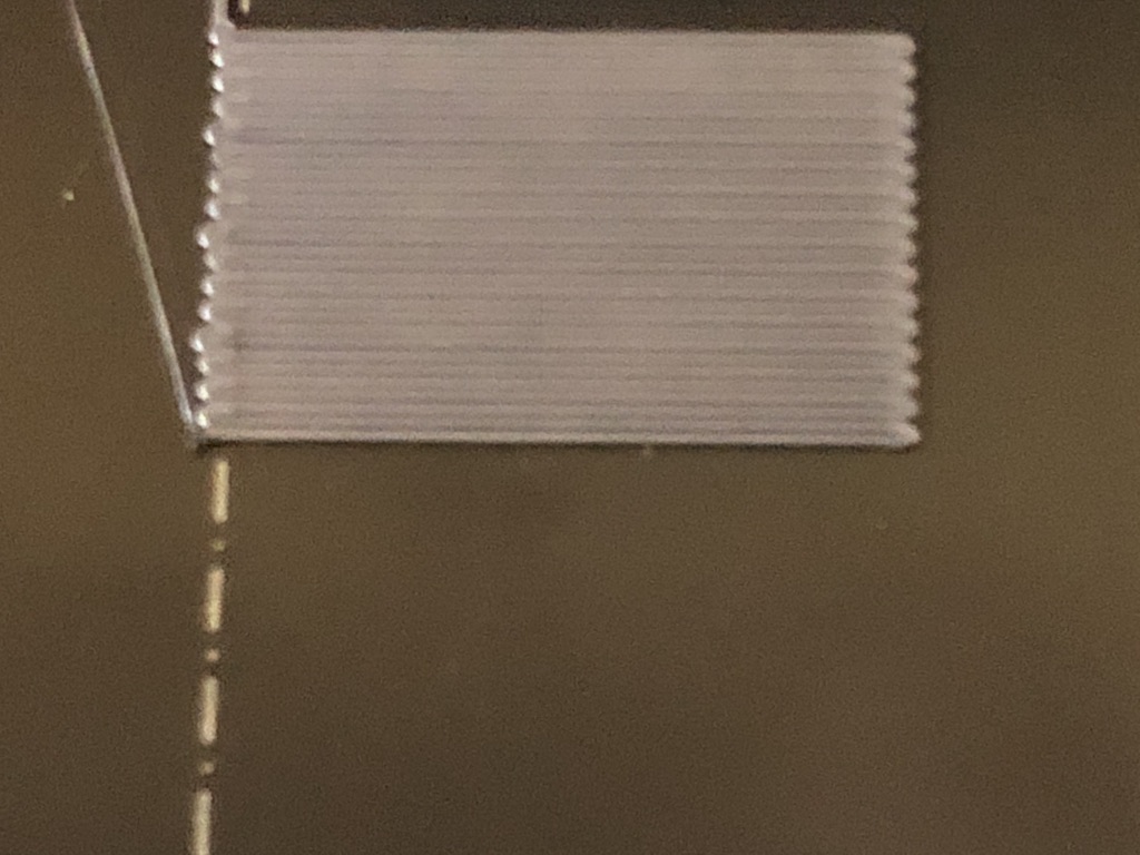
This is what I got this evening. I started with the calibration routine in the firmware, but then went to the large square printed in the middle (in the link from @JustMe3D). I feel like I'm getting contradictory results. Z adjustment is with each photo:
Z = -1.250. I could easily feel the ribbed surface from the lines on each printed line.
Z = -1.350. Things started to mess up. You can see how, on the left and right of the middle, I got globs or glitches or something. (Is there a technical term for those messes?) And at this point, the zig-zag line in the rest of the test was tough to pull up. It was so thin that as I pulled, it'd keep breaking apart.
Z = -1.450. Messier and pulling up the one line zig-zag was a major pain because it kept breaking up on me every time I pulled part of it up. (Or is that normal because I should be using something to remove it from the bed?) On the one hand, this looks worse, but it also looks like the messes here stick up less (other than that one at the top of the picture) than the messes in the last one at -1.350.

1st big square. Bottom half at -1.300. (Oops - or -1.350? I remember adjusting it .025 and just realized I might have messed up.) The -1.325 looks better, but it looks like it took time for it to adapt or change.

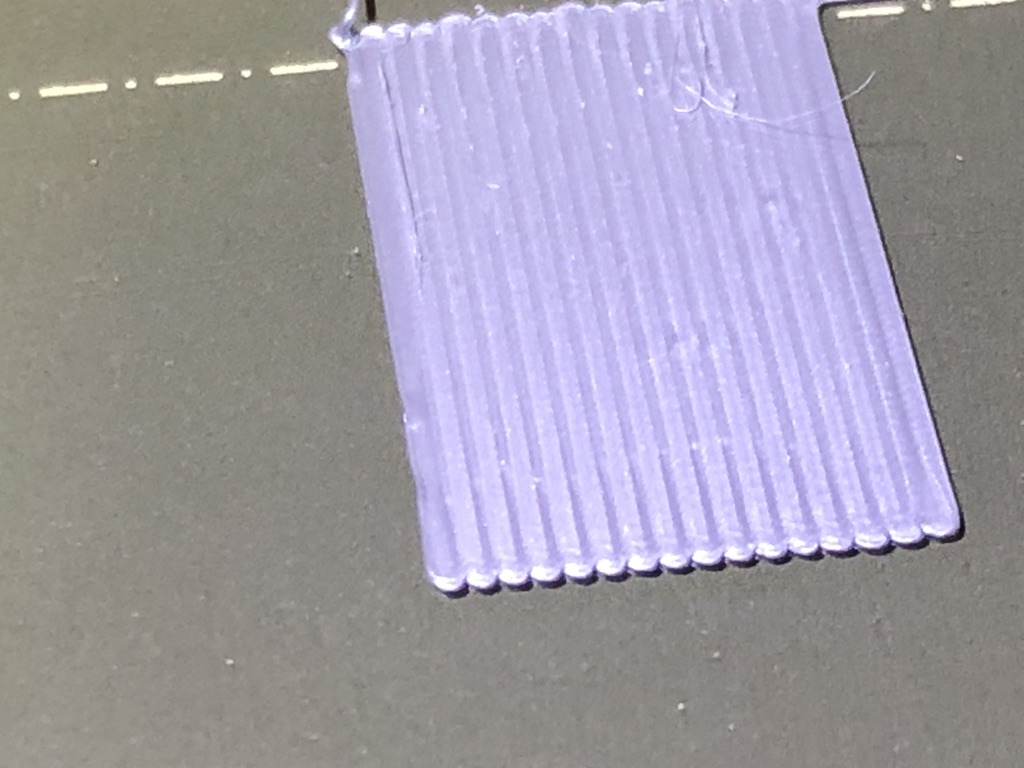
When I compare these to the example here (in the first photo, with blue filament), it looks like the head is still too high. Earlier I tried -1.500 and it was messy but, again, comparing it to the example photo, that looks like it's too high. However, from about -1.350 to -1.500, the zig-zag line was so thin I couldn't easily pull it off the print bed, so that has made me think maybe it's too close and there's something else I need to adjust.
Also, when I printed at -1.000, a day or so ago, there were no glitches - but the top was definitely not smooth. It was regular and ribbed, even more than at -1.250, as seen here.
So should I keep going beyond -1.450 or -1.500? or do I need to back off and try something around -1.250?
RE: Just assembled and calibration prints have problems
The first one looks good to me. All others seem to be too low. I'd set the -1.250 from the first picture and call it a day. Start printing something fun and do not bother trying bigger and bigger rectangles. There are limits to how good your first layer can be all over the print bed. Goal should be to have it squish enough to get good adhesion and not so low that you accumulate material with the nozzle (like on the other pictures) and screw up the second layer. The first layer will never be perfect, for a couple of reasons and it does not have to be. If you ever print something that must be precise within a few dozen microns on z axis: print a raft or change the design. In all other cases, the primary function of the first layer is adhesion not perfection.
If at first you don't succeed, skydiving is not for you.
Find out why this is pinned in the general section!
RE: Just assembled and calibration prints have problems
I agree with Robin's assessment that -1.250 is as low as you want to get. I'd be adjusting higher. The ridges could be caused by too much smooshing. Going lower is obviously not removing them. The lifting artifacts are the head dragging material up.
I like using the bigger squares to change and observe the differences. The default Prusa pattern lets you dial inthe height from way up until it touches and gives you little time to adjust in the small rectangle.
Looking at the pictures you posted, I'd start with -1.250, and part way through (1/5 of the way (?), enough to observe the print results under the moving head), move the head up to -1.150 and see how it looks. Does it look better? If yes, go up a little more, try -1.050 for 1/5 the print. If not, go down to -1.200 for 1/5 the print. By now you'll start to get the hang of what is better. Once the differences are negligible in your eyes your dialed in.
The print tearing apart as you peel it from the plate is a good indication that you are at the wrong value. Once I dial it in I cannot separate the print lines by hand.
I look for smoothing, though as you noted, it will never be glass smooth. I look for closure at the ends of the turns. Not enough smooshing, i.e. too high, leaves openings at the turns because the width of the bead is too narrow.
The negative numbers cause confusion, so keep those straight in your head. To raise the head, you use a larger number, -1.250 is larger than -1.300 and changing from -1.300 to -1.250 raises the head. Writing the values on the prints is a good idea. I do this as well and it helps me keep the numbers straight. And, recall when I dialed up or down.
As Robin implies, you can be too maniacal about this, but that's your call. BTW, with my eyes, I use a magnifying glass to notice the different properties. I changed by prints between two materials and associated sheets, adjusted the z-axis number and got a perfect adherence to the sheet. I like that ability.
Also, write the final value down some place (z axis is a function of material and plate). The MK3S+ has a plate setting on the front panel, but you need to set it and use it when changing plates. The method, to me, is not intuitive. But, once set, you select a plate and the z-value of the print changes and adjusts if you use live z adjustments.
RE: Just assembled and calibration prints have problems
There are limits to how good your first layer can be all over the print bed.
Okay. That helps. When I look at the demo photo in my link, it looks perfectly smooth and flat on the top, so I thought something was wrong because I wasn't getting that.
Goal should be to have it squish enough to get good adhesion and not so low that you accumulate material with the nozzle (like on the other pictures) and screw up the second layer.
I wasn't sure but that's what I thought was happening in the later layers - that material was sticking to the nozzle or that the nozzle itself was scraping and messing up what it had already put down.
The first layer will never be perfect, for a couple of reasons and it does not have to be.
Okay, glad to hear that! So even with the ribbing that shows up on that layer, it doesn't mean that the rest of the print can't be smooth?
RE: Just assembled and calibration prints have problems
Okay, glad to hear that! So even with the ribbing that shows up on that layer, it doesn't mean that the rest of the print can't be smooth?
No. After the first layer the head moves up a set value, e.g. 0.20 mm. Notice that the second layer prints perpendicular to the first. You do not see the underlying ribbing, just the new layer's ribbing.
RE: Just assembled and calibration prints have problems
I like using the bigger squares to change and observe the differences. The default Prusa pattern lets you dial inthe height from way up until it touches and gives you little time to adjust in the small rectangle.
I've wondered about that and liked seeing the difference between the two sections of different adjustments in the big square I printed. I have a few ideas for what might make a terrific adjustment file, but I don't know if it's all something I can do in G-Code at this point. (I used to be a programmer, I still do a lot of stuff for my own use in Python, but I haven't had time to study G-Code yet and find out just what it can do other than move a print head or router around.)
The print tearing apart as you peel it from the plate is a good indication that you are at the wrong value. Once I dial it in I cannot separate the print lines by hand.
Thank you for the confirmation. It just seemed wrong that it would be so hard to pull it up like that!
The negative numbers cause confusion, so keep those straight in your head. To raise the head, you use a larger number, -1.250 is larger than -1.300 and changing from -1.300 to -1.250 raises the head. Writing the values on the prints is a good idea. I do this as well and it helps me keep the numbers straight. And, recall when I dialed up or down.
Yes, you're right. While I've seen a lot of people writing just 1250 or 1300, I make sure I include the decimal and a minus to keep it clear in my head. Even knowing that, it still feels seriously counter-intuitive. One reason I like the bigger squares is because it's easy to write values on them. Also, while I haven't done it yet, it's easy to make a mark on the side where I change from one value to the next.
Also, write the final value down some place (z axis is a function of material and plate). The MK3S+ has a plate setting on the front panel, but you need to set it and use it when changing plates. The method, to me, is not intuitive. But, once set, you select a plate and the z-value of the print changes and adjusts if you use live z adjustments.
At some point I must have had the head too low, since I've scratched this plate, once on each side. I've ordered a new one, so I guess I'll be dialing that in, as well. While I keep a clipboard with extra scratch paper in the shop, I'm going to take down a smaller notepad and keep it at my print station so I can keep notes like that nearby.