RE: Calibration
Mmh, maybe we're talking different things?!? When I say "move PINDA lower/higher", I mean unscrewing the screw that holds it in the extruder, moving it a bit up or down, then securing it again with the screw. So when you physically move the PINDA up in its holder, there will be a greater distance between nozzle and PINDA and thus when the extruder moves toward the sheet, at the point the PINDA triggers the nozzle will be closer to the sheet, and in turn the Live Z required to get a good first layer will be less negative. Seems logical to me, so maybe we're using the same word(s) with different interpretations?
In any case, a tool with a thickness of about 1.5 mm should yield a reasonable distance between nozzle and PINDA to get into a good Live Z range.
Huh, I just found this thread in which someone purports to have a printer on which lowering Live Z moves the nozzle up.... https://forum.prusa3d.com/forum/original-prusa-i3-mk3s-mk3-assembly-and-first-prints-troubleshooting/how-to-adjust-move-the-pinda-down/ but @joantabb's explanation in that thread seems consistent with my understanding of how the PINDA and its relationship to nozzle and Live Z works.
Formerly known on this forum as @fuchsr -- https://foxrun3d.com/
RE: Calibration
@fuchsr
As I understand it, the more negative you make the Z offset, the lower the nozzle is. You are subtracting from the current position. Am I wrong?
--------------------
Chuck H
3D Printer Review Blog
RE: Calibration
Yes, you're correct. The more negative the Live Z, the closer the nozzle is to the sheet. That's why I suspect we're actually agreeing but we're not quite aligned on how we talk about it.
To quote @joantabb from the link I referred to in my previous post:
>Your pinda measures a safe distance from the build plate, to the pinda probe tip. and stops the downward travel of the Z axis... this means that the distance between the nozzle which is fixed to move up and down in relation to the Pinda, will be a safe distance above the build plate, but because of the initial set up, the Nozzle tip will be closer to the build plate than the pinda tip. at this stage the Z height will be reported as 0.0 mm BUT the nozzle will always be too high. so you now need to do Live Z adjustment. and adjust the nozzle closer to the build plate
So, given a fixed distance between PINDA and nozzle tip, the nozzle will stop at a certain distance away from the sheet. You can then lower the nozzle -- with increasingly more negative Z -- to perfect your first layer. Exactly what you said. I think we're on the same page so far.
Now, my point is, if you change the actual physical distance between PINDA and nozzle tip by moving the PINDA higher (not the whole extruder, just the PINDA probe in its hotend mount), AND the PINDA triggers at the same distance from the sheet, the nozzle will now be closer to the sheet when that happens. So to get to the same good first layer, you need to adjust Live Z less into the negative territory than before, so your Live Z will be less negative to have the same first layer quality.
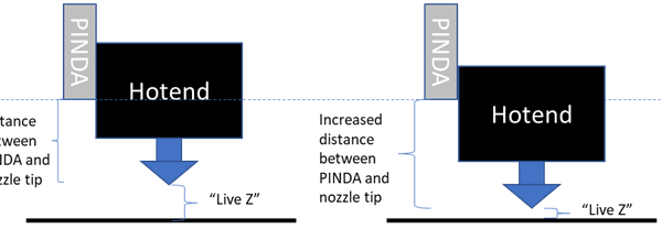
I drew this quick illustration to explain.
[Not sure why the picture is truncated, check out the imgur link]
On the left, you see the "before".
There's a certain distance between nozzle and PINDA, and there's a certain distance at which the PINDA says, you're close enough to the sheet. From there, you can then adjust Live Z--the distance between nozzle tip and sheet-- down (into more negative territory) until your first layer is perfect.
So let's say, I need a Live Z close to -2 (or more) to get the first layer right. In that case, I would reposition the PINDA upward in its hotend mount. On the right, you see "after" the adjustment. The distance between Pinda and nozzle tip has now increased because I repositioned the PINDA. The PINDA will still trigger and stop extruder movement at the same distance from the sheet. But as a result of repositioning the PINDA, the nozzle will now be closer to the sheet when that happens. This establishes a new starting point (0) for Live Z adjustment, so to get the same good first layer as before, I need to move the nozzle down less, or in other words, the Live Z will be less negative, e.g, if it was -2 before, it may now be -1.
The recommended distance between PINDA and nozzle tip is 1.5 mm for the SuperPINDA and was 0.8 mm for the older version.
Sorry for this professorial extravaganza but I hope it helps bring us on the same page.
Formerly known on this forum as @fuchsr -- https://foxrun3d.com/
RE: Calibration
@fuchsr
We may have been saying the same thing but not understanding one another. It is so easy to get confused.
--------------------
Chuck H
3D Printer Review Blog
RE: Calibration
Of course we were on the same page after all!🙌
Live Z being negative doesn't really help. Not the most intuitive.
Formerly known on this forum as @fuchsr -- https://foxrun3d.com/
RE: Calibration
@malabor
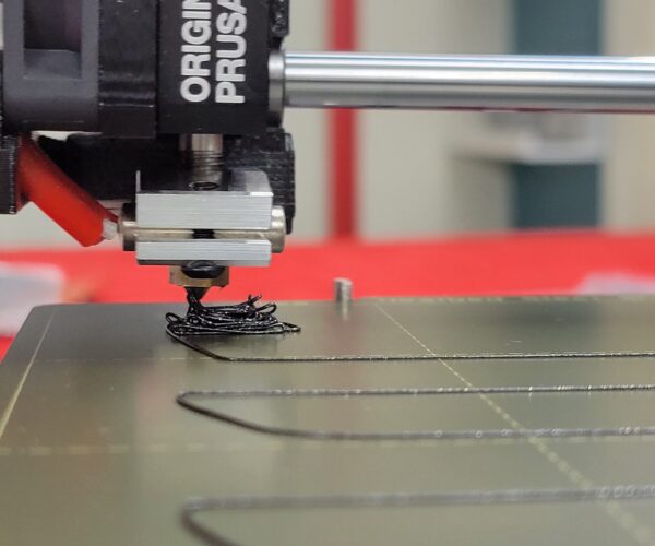
From the picture it looks like your filament is not squished at all, looks perfectly round, so your nozzle needs to go lower.
To properly adjust Live Z, don't use the in-built method, as the small square is hard to read, especially if you're not experienced. Use this instead: https://forum.prusa3d.com/forum/original-prusa-i3-mk3s-mk3-assembly-and-first-prints-troubleshooting/life-adjust-z-my-way/
To quote @bobstro:
> In general, start high (less negative) and work lower (more negative) in large increments (e.g. 0.1mm) until the filament starts to stick on its own. When you've got your Live-Z setting adjusted properly, you should be able to gently rub the extruded lines on the PEI surface without dislodging them. Then start lowering (more negative) the level until there are no gaps between layers. You should not be able to peel the lines apart after printing, but the top should be regular.
A good Live Z should be anywhere between -0.5 and -1.5, depending on printer and sheet. If you get close to -2.0 I would reposition the PINDA higher.
Textured sheets are thinner than smooth sheets and require lower Live Z.
Even within one type (e.g. smooth) two sheets may differ in enough in thickness due to manufacturing tolerances to warrant different Live Z.
Formerly known on this forum as @fuchsr -- https://foxrun3d.com/
RE: Calibration
@fuchsr
Thanks. I just wanted to make sure I understood what you were saying. I am tired today. No quite as clear thinking.
This as a great thread.
I have one printer where the heat has warped the PINDA holder. That creates a unique problem.
--------------------
Chuck H
3D Printer Review Blog
RE: Calibration
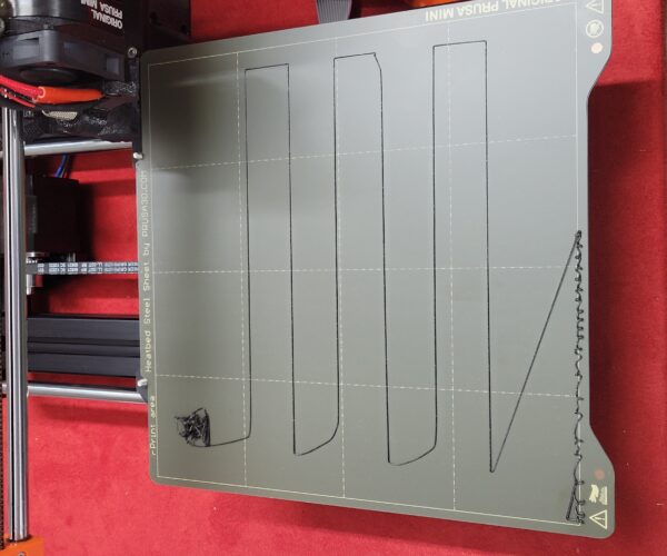
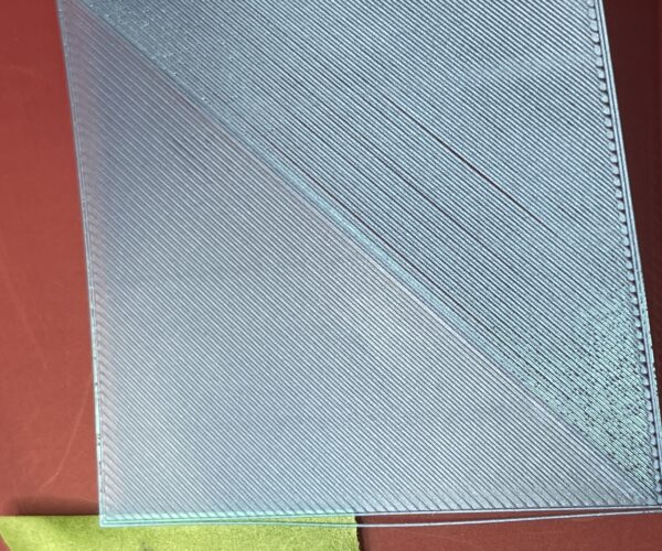
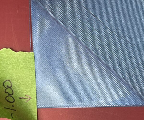
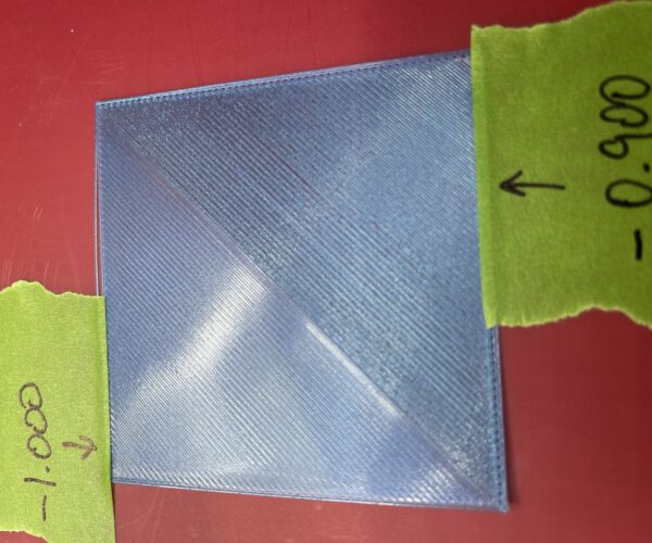
Done some setup this eve by moving the spinda up a little and then performing a series of prints. Started at -0.500 and moved down all the way to -1.000 at which point I got a perfect first layer. See pics.
RE: Calibration
High five!
Formerly known on this forum as @fuchsr -- https://foxrun3d.com/
RE: Calibration
@fuchsr
yep thanks to everyones help on here....
RE: Calibration
I mostly agree with @fuchsr.
@cwbullet: How I see it, the design logic behind it is straightforward. With this I can verify the directions by heart at any time. Please correct me, if I am wrong.
The z-homing shall be done so that no sensor touches the clean bed surface. At the same time it shall be reliable, durable, as direct as possible and easy and safe to use. So, Prusa opted for an inductive proximity sensor like the S(Pinda) that triggers at a (sensor specific) distance to the ferrous metal sheet. The sensor's output signal then flips between 0 and 1. This type is quite common in the industry. See eg:
https://www.eandm.com/Products/Content/Siemens/Training/Siemens_Courses/snrs_2.pdf
After assembly, during all calibration, you want to be sure, not to ram the nozzle into the bed. So the nozzle has to be well above the trigger point
of the sensor. All 3 points (nozzle, sensor and its trigger point) always move together.
During print, you do not want your sensor to scratch the printed part surface either. Therefore, the nozzle also has to be well below the sensor itself.
In order to make it easy for the user to adjust the sensor height position, you want to maximize its allowed tolerance. As a rule of thumb, you distribute both distances symmetrically and attach the sensor at a height, where the nozzle is roughly halfway between sensor and its trigger point below.
Considering that the inductive sensor does not detect the non-ferrous bed surface layer (foil, powder coating, tape etc.), you shift the nominal nozzle position slightly upwards (relative to the sensor) by the thickest expected bed surface layer. Since the nozzle height is rather fixed on the extruder, instead you shift the sensor (and with it its trigger point with it) in the opposite direction, that is, slightly downwards.
During z and meshbed leveling, again, you want to be safe not to ram your nozzle into the bed. So, no offset is applied then. Zero pos is trigger height.
For printing though, this is intentionally too high. Therefore you have to lower the nozzle by an offset. Positive z points upwards. So, the offset to get down towards the underside of the first layer (part height 0) must be negative. This is the reason, why a positive value does not make any sense.
imaginary example:
Say, the sensor's frontal trigger distance were 2.4mm.
To initially have the nozzle halfway down, 1.2mm below the sensor, put the sensor 1.2mm above the nozzle.
If your thickest bed layer is 0.4mm, shift the sensor 0.4mm downwards.
Result: Distance between nozzle and sensor is 0.8mm. As a consequence,
the resulting distance between nozzle and sheet metal now is 1.6 when at trigger height.
Say, the currently used sheet has 0.2mm non-metallic layer on top.
Then at trigger height, the distance between nozzle and sheet layer is 1.4mm.
In order to get down to kiss contact between nozzle and sheet layer surface
you have to apply a nominal offset of -1.4mm.
Depending on tolerances in parts and assembly within the chain of parts from nozzle to sensor, the sensor trigger tolerance and tolerance in sheet layer thickness, that offset is different for every individual printer and sheet. It is independent from the gcode. The latter is supposed to be portable and contains all layer heights including the first.
That's basically it.
Of course, this is a bit simplified and ignores hysteresis, temperature compensation, meshbed correction by user etc. but hopefully makes the point in an alternative way to the good explanation by @fuchsr.
Since the sensing area in front of the circular sensor face ist roughly conical, the sensor's second purpose is to detect laterally the positions of the four ferrous marker integrated into the bed carriage plate during xyz-calibration and calculate skew from those. Please ask yourself: How does Prusa avoid ramming into the bed carriage, during calibration when the spring steel sheet is not yet on the printer? Apart from that, this is another reason, why you want to have the nozzle slightly higher up.
I am glad, that Prusa did not invert the value but actually keeps the direction of the offset consistent with the coordinate system. This is a point, my opinion differs from @fuchsr.
Apart from that, I'd rather not try to rub the zig-zag lines away, especially not with a finger since it is practically inevitable that you touch the bed. That means, you have to clean the bed with dishwasher and rinse again. Otherwise the adhesion during next print will become problematic.
Have a nice day.
RE: Calibration
@blauzahn
I think you are right. @Eirlink I am glad it is working.
I had a rough week. I am having 2 fingers of bourbon and relaxing. Have a great day!
--------------------
Chuck H
3D Printer Review Blog
RE: Calibration
@malabor
I had the exact same issue. After many calibration attempts I finally put a level on the X axis bar and found that it was off about 1/8th inch on the left side. I carefully bent the main column to correct this. I also adjusted my Z to -1.5. After this it printed pretty good. Hope this helps.
RE: Calibration
@rgamble
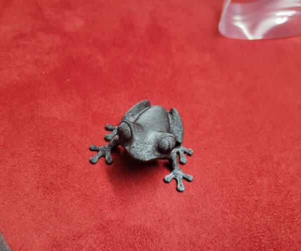
Boom! That seems to have fixed it. I didn't even think to check the level on the x. Sure enough, it was out. So I moved the sensor up, bent the arm into level and adjusted my live z using the above mentioned file as a guide. Printed beautifully!
Printed off the logo and the tree frog last night. They turned out great! 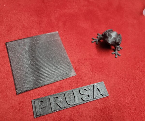
RE: Calibration
Glad you got it worked out.
I just received my Mini (semi-assembled version) and after I ran it through first layer calibration, I found that even at -2.0, the Z-axis was not getting close enough with the nozzle to the print surface. I had to adjust the MINDA sensor up a couple of notches then re-run the first layer calibration. Maybe PRUSA assemblers have very thin credit cards for their standard sensor height??
Works fine now though! Cheers.
RE: Calibration
I had another big fail yesterday and thought I had destroyed my mini+. I wanted to try for the first time a big piece, you know, just to see how it would go. Well, I got the file, sliced it in half (it was way to tall for my mini+ printer) and thought, "Yeah, that'll be great". I had no idea that you actually had to pay attention to the levels of the print pieces or the bottom print service. I'm such a newbie! What a mess it made! It got PLA clogged up in a giant blob on the extruder and all over the MINDA. It took me a while to get it all cleaned up and re-calibrated. I've got it dialed back in for the moment and am retrying the piece. This time I've sliced it into 4 pieces, each with the same height and a flat bottom service. It's printing the first layer as of this post, so wish me luck!!
