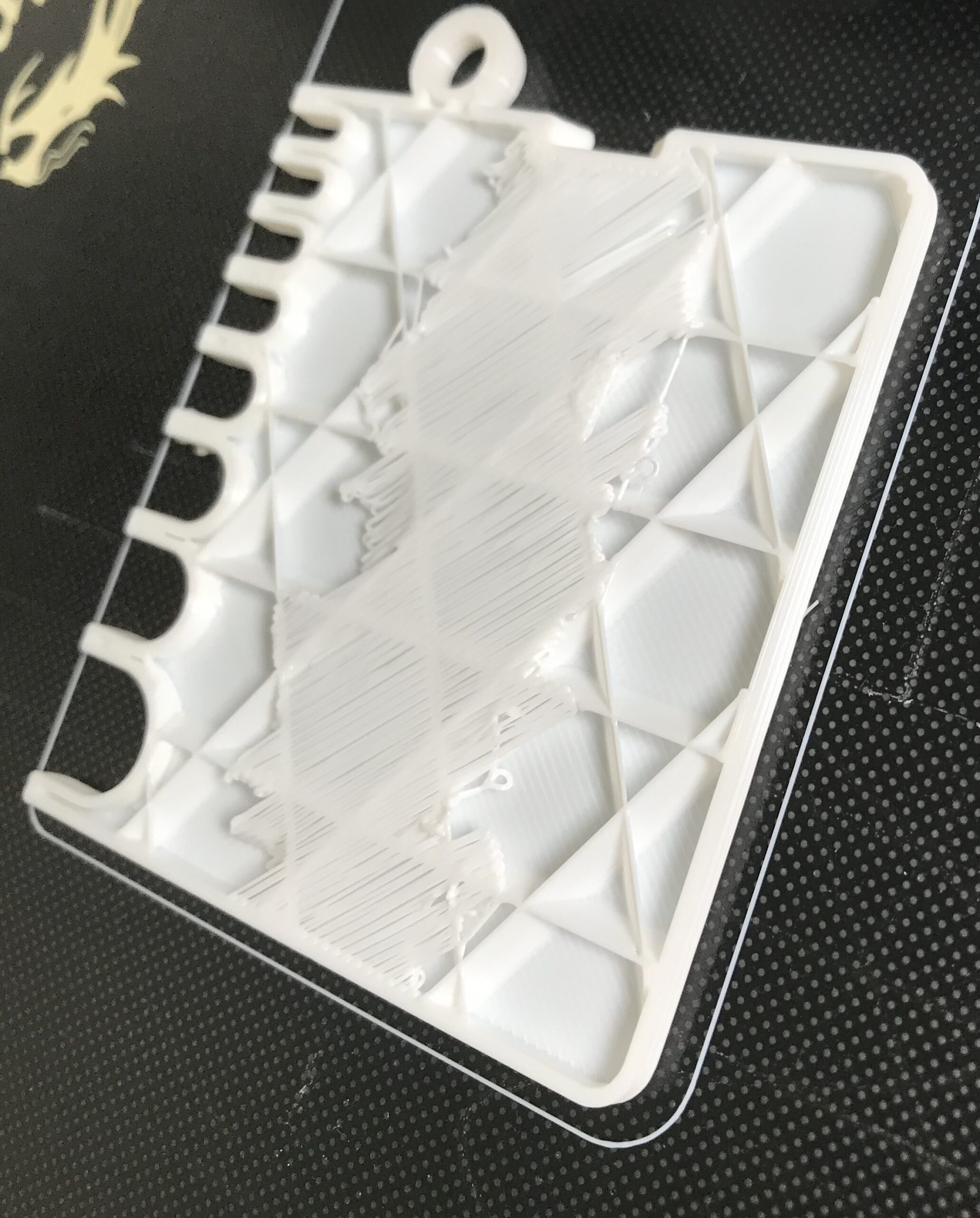
Unsupported bridge ends at Bridge Infill edges with Adaptive Cubic
I used 10% adaptive cubic infill and noticed this sloppy layer in the print. Shouldn't the infill bridging anchor on the infill pattern? It seems completely separate, with a hexagonal grid pattern in free space, rather than tagging the bridges to infill along the path of travel that I would expect. Attached please find a pic and screenshot of the sagging Bridge Infill, the PrusaSlicer 2.5.0 plan that produced it, and a chunk of settings from the gcode file.
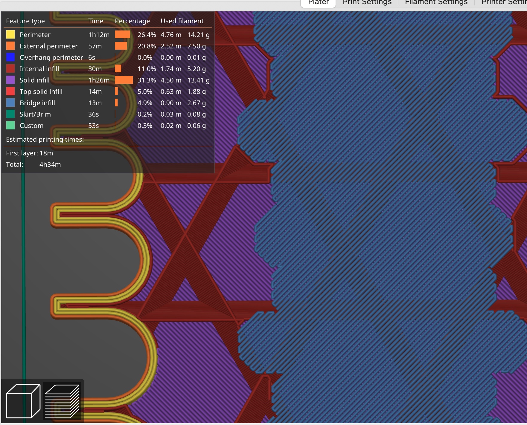
I saw https://forum.prusa3d.com/forum/original-prusa-i3-mk3s-mk3-how-do-i-print-this-printing-help/low-density-infill-and-planes-on-top-of-it/#post-483370 that suggested different patterns for a similar problem. But it looks like the Adaptive Cubic Bridge infill routine is trying to produce a convoluted perimeter in free space that wouldn't work well to bridge between.
Am I missing a setting or something?
Sagging unsupported bridge infill with/Adaptive cubic Slicer plan for adaptive cubic bridge infill showing unsupported edges
; generated by PrusaSlicer 2.5.0+MacOS-x64 on 2022-09-28 at 22:51:58 UTC
;
; external perimeters extrusion width = 0.45mm
; perimeters extrusion width = 0.45mm
; infill extrusion width = 0.45mm
; solid infill extrusion width = 0.45mm
; top infill extrusion width = 0.40mm
; first layer extrusion width = 0.42mm
; external perimeters extrusion width = 0.45mm
; perimeters extrusion width = 0.45mm
; infill extrusion width = 0.45mm
; solid infill extrusion width = 0.45mm
; top infill extrusion width = 0.40mm
; first layer extrusion width = 0.42mm
...
;END gcode for filament
; filament used [mm] = 15078.89
; filament used [cm3] = 36.27
; filament used [g] = 44.97
; filament cost = 0.90
; total filament used [g] = 44.97
; total filament cost = 0.90
; estimated printing time (normal mode) = 4h 34m 9s
; prusaslicer_config = begin
; avoid_crossing_perimeters = 0
; avoid_crossing_perimeters_max_detour = 0
; bed_custom_model =
; bed_custom_texture =
; bed_shape = 5x0,215x0,215x220,5x220
; bed_temperature = 60
; before_layer_gcode = ;BEFORE_LAYER_CHANGE\nG92 E0\n;{layer_z}\n\n
; between_objects_gcode =
; bottom_fill_pattern = monotonic
; bottom_solid_layers = 4
; bottom_solid_min_thickness = 0
; bridge_acceleration = 250
; bridge_angle = 0
; bridge_fan_speed = 100
; bridge_flow_ratio = 0.95
; bridge_speed = 25
; brim_separation = 0
; brim_type = outer_only
; brim_width = 0
; clip_multipart_objects = 1
; color_change_gcode = M600
; compatible_printers_condition_cummulative = "printer_model=~/(ENDER|CR|SERMOON).*/ and nozzle_diameter[0]==0.4";printer_notes=~/.*PRINTER_VENDOR_CREALITY.*/
; complete_objects = 0
; cooling = 1
; cooling_tube_length = 5
; cooling_tube_retraction = 91.5
; default_acceleration = 500
; default_filament_profile = "Generic PLA @CREALITY"
; default_print_profile = 0.16mm OPTIMAL @CREALITY
; deretract_speed = 40
; disable_fan_first_layers = 1
; dont_support_bridges = 1
; draft_shield = disabled
; duplicate_distance = 6
; elefant_foot_compensation = 0.1
; end_filament_gcode = "; Filament-specific end gcode \n;END gcode for filament\n"
; end_gcode = {if max_layer_z < max_print_height}G1 Z{z_offset+min(max_layer_z+2, max_print_height)} F600 ; Move print head up{endif}\nG1 X5 Y{print_bed_max[1]*0.8} F{travel_speed*60} ; present print\n{if max_layer_z < max_print_height-10}G1 Z{z_offset+min(max_layer_z+70, max_print_height-10)} F600 ; Move print head further up{endif}\n{if max_layer_z < max_print_height*0.6}G1 Z{max_print_height*0.6} F600 ; Move print head further up{endif}\nM140 S0 ; turn off heatbed\nM104 S0 ; turn off temperature\nM107 ; turn off fan\nM84 X Y E ; disable motors
; ensure_vertical_shell_thickness = 1
; external_perimeter_extrusion_width = 0.45
; external_perimeter_speed = 25
; external_perimeters_first = 0
; extra_loading_move = -2
; extra_perimeters = 0
; extruder_clearance_height = 34
; extruder_clearance_radius = 47
; extruder_colour = #FCE94F
; extruder_offset = 0x0
; extrusion_axis = E
; extrusion_multiplier = 1
; extrusion_width = 0.45
; fan_always_on = 1
; fan_below_layer_time = 100
; filament_colour = #DDDDDD
; filament_cooling_final_speed = 3.4
; filament_cooling_initial_speed = 2.2
; filament_cooling_moves = 4
; filament_cost = 20
; filament_density = 1.24
; filament_diameter = 1.75
; filament_load_time = 0
; filament_loading_speed = 28
; filament_loading_speed_start = 3
; filament_max_volumetric_speed = 15
; filament_minimal_purge_on_wipe_tower = 15
; filament_notes = ""
; filament_ramming_parameters = "120 100 6.6 6.8 7.2 7.6 7.9 8.2 8.7 9.4 9.9 10.0| 0.05 6.6 0.45 6.8 0.95 7.8 1.45 8.3 1.95 9.7 2.45 10 2.95 7.6 3.45 7.6 3.95 7.6 4.45 7.6 4.95 7.6"
; filament_settings_id = "Generic PLA @CREALITY"
; filament_soluble = 0
; filament_spool_weight = 0
; filament_toolchange_delay = 0
; filament_type = PLA
; filament_unload_time = 0
; filament_unloading_speed = 90
; filament_unloading_speed_start = 100
; filament_vendor = Generic
; fill_angle = 45
; fill_density = 10%
; fill_pattern = adaptivecubic
; first_layer_acceleration = 0
; first_layer_acceleration_over_raft = 0
; first_layer_bed_temperature = 60
; first_layer_extrusion_width = 0.42
; first_layer_height = 0.2
; first_layer_speed = 20
; first_layer_speed_over_raft = 30
; first_layer_temperature = 210
; full_fan_speed_layer = 0
; fuzzy_skin = none
; fuzzy_skin_point_dist = 0.8
; fuzzy_skin_thickness = 0.3
; gap_fill_enabled = 1
; gap_fill_speed = 30
; gcode_comments = 0
; gcode_flavor = marlin
; gcode_label_objects = 0
; gcode_resolution = 0.0125
; gcode_substitutions =
; high_current_on_filament_swap = 0
; host_type = octoprint
; infill_acceleration = 0
; infill_anchor = 600%
; infill_anchor_max = 50
; infill_every_layers = 1
; infill_extruder = 1
; infill_extrusion_width = 0.45
; infill_first = 0
; infill_only_where_needed = 0
; infill_overlap = 25%
; infill_speed = 50
; interface_shells = 0
; ironing = 0
; ironing_flowrate = 15%
; ironing_spacing = 0.1
; ironing_speed = 15
; ironing_type = top
; layer_gcode = ;AFTER_LAYER_CHANGE\n;{layer_z}
; layer_height = 0.2
; machine_limits_usage = time_estimate_only
; machine_max_acceleration_e = 5000
; machine_max_acceleration_extruding = 500
; machine_max_acceleration_retracting = 1000
; machine_max_acceleration_travel = 1500,1250
; machine_max_acceleration_x = 500
; machine_max_acceleration_y = 500
; machine_max_acceleration_z = 100
; machine_max_feedrate_e = 60
; machine_max_feedrate_x = 500
; machine_max_feedrate_y = 500
; machine_max_feedrate_z = 10
; machine_max_jerk_e = 5
; machine_max_jerk_x = 8
; machine_max_jerk_y = 8
; machine_max_jerk_z = 0.4
; machine_min_extruding_rate = 0
; machine_min_travel_rate = 0
; max_fan_speed = 100
; max_layer_height = 0.28
; max_print_height = 250
; max_print_speed = 100
; max_volumetric_extrusion_rate_slope_negative = 0
; max_volumetric_extrusion_rate_slope_positive = 0
; max_volumetric_speed = 0
; min_bead_width = 85%
; min_fan_speed = 100
; min_feature_size = 25%
; min_layer_height = 0.08
; min_print_speed = 15
; min_skirt_length = 4
; mmu_segmented_region_max_width = 0
; notes =
; nozzle_diameter = 0.4
; only_retract_when_crossing_perimeters = 0
; ooze_prevention = 0
; output_filename_format = {input_filename_base}_{print_time}_{digits(layer_height,1,2)}mm_{temperature[0]}C_{filament_type[0]}_{printer_model}.gcode
; overhangs = 1
; parking_pos_retraction = 92
; pause_print_gcode =
; perimeter_acceleration = 0
; perimeter_extruder = 1
; perimeter_extrusion_width = 0.45
; perimeter_generator = arachne
; perimeter_speed = 40
; perimeters = 3
; physical_printer_settings_id = CE3V2_octo
; post_process =
; print_settings_id = 0.20mm NORMAL @CREALITY
; printer_model = ENDER3V2
; printer_notes = Don't remove the following keywords! These keywords are used in the "compatible printer" condition of the print and filament profiles to link the particular print and filament profiles to this printer profile.\nPRINTER_VENDOR_CREALITY\nPRINTER_MODEL_ENDER3V2\nPRINTER_HAS_BOWDEN
; printer_settings_id = Creality Ender-3 V2
; printer_technology = FFF
; printer_variant = 0.4
; printer_vendor =
; raft_contact_distance = 0.1
; raft_expansion = 1.5
; raft_first_layer_density = 90%
; raft_first_layer_expansion = 3
; raft_layers = 0
; remaining_times = 0
; resolution = 0
; retract_before_travel = 2
; retract_before_wipe = 70%
; retract_layer_change = 1
; retract_length = 5
; retract_length_toolchange = 1
; retract_lift = 0
; retract_lift_above = 0
; retract_lift_below = 0
; retract_restart_extra = 0
; retract_restart_extra_toolchange = 0
; retract_speed = 60
; seam_position = nearest
; silent_mode = 0
; single_extruder_multi_material = 0
; single_extruder_multi_material_priming = 0
; skirt_distance = 3
; skirt_height = 2
; skirts = 1
; slice_closing_radius = 0.049
; slicing_mode = regular
; slowdown_below_layer_time = 20
; small_perimeter_speed = 25
; solid_infill_below_area = 0
; solid_infill_every_layers = 0
; solid_infill_extruder = 1
; solid_infill_extrusion_width = 0.45
; solid_infill_speed = 40
; spiral_vase = 0
; standby_temperature_delta = -5
; start_filament_gcode = "; Filament gcode\n"
; start_gcode = G90 ; use absolute coordinates\nM83 ; extruder relative mode\nM140 S{first_layer_bed_temperature[0]} ; set final bed temp\nM104 S150 ; set temporary nozzle temp to prevent oozing during homing\nG4 S10 ; allow partial nozzle warmup\nG28 ; home all axis\nG1 Z50 F240\nG1 X2 Y10 F3000\nM104 S{first_layer_temperature[0]} ; set final nozzle temp\nM190 S{first_layer_bed_temperature[0]} ; wait for bed temp to stabilize\nM109 S{first_layer_temperature[0]} ; wait for nozzle temp to stabilize\nG1 Z0.28 F240\nG92 E0\nG1 Y140 E10 F1500 ; prime the nozzle\nG1 X2.3 F5000\nG92 E0\nG1 Y10 E10 F1200 ; prime the nozzle\nG92 E0
; support_material = 0
; support_material_angle = 0
; support_material_auto = 1
; support_material_bottom_contact_distance = 0
; support_material_bottom_interface_layers = -1
; support_material_buildplate_only = 0
; support_material_closing_radius = 2
; support_material_contact_distance = 0.15
; support_material_enforce_layers = 0
; support_material_extruder = 0
; support_material_extrusion_width = 0.38
; support_material_interface_contact_loops = 0
; support_material_interface_extruder = 0
; support_material_interface_layers = 2
; support_material_interface_pattern = rectilinear
; support_material_interface_spacing = 0.2
; support_material_interface_speed = 100%
; support_material_pattern = rectilinear
; support_material_spacing = 2
; support_material_speed = 40
; support_material_style = grid
; support_material_synchronize_layers = 0
; support_material_threshold = 40
; support_material_with_sheath = 0
; support_material_xy_spacing = 60%
; temperature = 205
; template_custom_gcode =
; thick_bridges = 1
; thin_walls = 0
; threads = 8
; thumbnails =
; thumbnails_format = PNG
; toolchange_gcode =
; top_fill_pattern = monotonic
; top_infill_extrusion_width = 0.4
; top_solid_infill_speed = 30
; top_solid_layers = 5
; top_solid_min_thickness = 0
; travel_speed = 150
; travel_speed_z = 0
; use_firmware_retraction = 0
; use_relative_e_distances = 1
; use_volumetric_e = 0
; variable_layer_height = 1
; wall_distribution_count = 1
; wall_transition_angle = 10
; wall_transition_filter_deviation = 25%
; wall_transition_length = 100%
; wipe = 1
; wipe_into_infill = 0
; wipe_into_objects = 0
; wipe_tower = 0
; wipe_tower_bridging = 10
; wipe_tower_brim_width = 2
; wipe_tower_no_sparse_layers = 0
; wipe_tower_rotation_angle = 0
; wipe_tower_width = 60
; wipe_tower_x = 170
; wipe_tower_y = 140
; wiping_volumes_extruders = 70,70
; wiping_volumes_matrix = 0
; xy_size_compensation = 0
; z_offset = 0
; prusaslicer_config = end
Best Answer by Neophyl:
Please help us to help you. Posting big long lists of settings is difficult to work with. As wll as making the forum posts almost unreadable due to the amount of scrolling. When asking for help please attach a ZIPPED up prusa slicer project file. File>Save As. This will save a *.3mf file. This 3mf file is a snapshot of your setup. It contains all 3 profiles, the model and other things like any modifiers, variable layer heights etc. It allows us to simply load it and have exactly the same slicing settings you have. We can also slice and make use of the various preview options. Its the single easiest way to debug issues.
It must be zipped or the forum doesn't accept the file type though.
That said, no you aren't missing a setting. Prusa Slicer doesnt do what you describe. The infill laid down is shaped based on the layers above and extends outwards so there should, in theory, be enough so that it covers a suitable area for the layers above to be printed on.
There are multiple issues open on github about this already. For example https://github.com/prusa3d/PrusaSlicer/issues/569 or https://github.com/prusa3d/PrusaSlicer/issues/7006
Super Slicer (a fork of PS) has a setting for this (several options actually). If you are using PS though then one manual work around is to add in a modifier at the correct place with a higher infill density/type to act as a supporting layer.
RE: Unsupported bridge ends at Bridge Infill edges with Adaptive Cubic
Please help us to help you. Posting big long lists of settings is difficult to work with. As wll as making the forum posts almost unreadable due to the amount of scrolling. When asking for help please attach a ZIPPED up prusa slicer project file. File>Save As. This will save a *.3mf file. This 3mf file is a snapshot of your setup. It contains all 3 profiles, the model and other things like any modifiers, variable layer heights etc. It allows us to simply load it and have exactly the same slicing settings you have. We can also slice and make use of the various preview options. Its the single easiest way to debug issues.
It must be zipped or the forum doesn't accept the file type though.
That said, no you aren't missing a setting. Prusa Slicer doesnt do what you describe. The infill laid down is shaped based on the layers above and extends outwards so there should, in theory, be enough so that it covers a suitable area for the layers above to be printed on.
There are multiple issues open on github about this already. For example https://github.com/prusa3d/PrusaSlicer/issues/569 or https://github.com/prusa3d/PrusaSlicer/issues/7006
Super Slicer (a fork of PS) has a setting for this (several options actually). If you are using PS though then one manual work around is to add in a modifier at the correct place with a higher infill density/type to act as a supporting layer.
RE:
Thanks. That all makes sense. test-test: BridgeInfillEdgesSagging (zipped .3mf file)
(I see that I am unable to edit that post, but I can edit this post.)
I now see that the last post in the thread I had linked highlights that the bridge infill is based on the layers above, not the support below.
RE:
Furthermore...
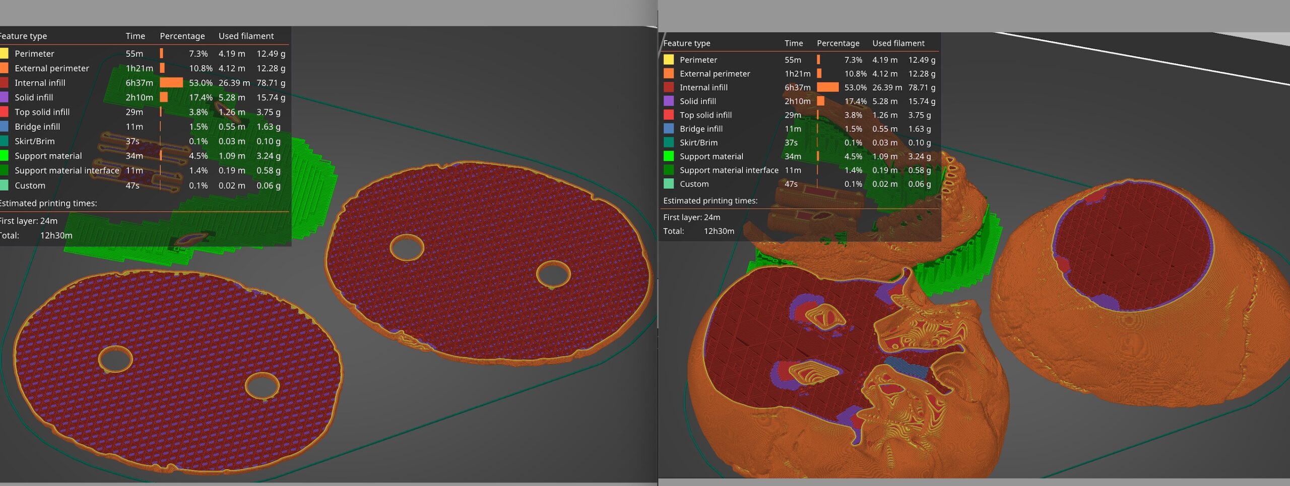
Approaching the problem from the infill side rather than the bridge infill perimeter side, I saw that the Adaptive Cubic infill percentage specifies the maximum density, and thins downwards from there. If you are having sagging problems, consider the much higher maximum density infills, (30-40-50-60%) and investigate how well they adapt downwards from there. Looking at another print, Adaptive Cubic with 99% infill compared to 20% infill used only 2.3x the filament and took 3.45x the time, while also eliminating significant solid infill and providing much better support for the remaining solid infill--Doubling or quadrupling the Adaptive infill doesn't cost 2 or 4 times the resources as one might expect from non-adaptive infill.
RE: Unsupported bridge ends at Bridge Infill edges with Adaptive Cubic
That's right and can easily get you. Because it's adaptive, infill percentage will change and what you specify as infill percentage is the maximum it will use at the top and thin downwards from there. I wish it was the other way round. I usually end up using 30 to 40 percent or so.
Formerly known on this forum as @fuchsr -- https://foxrun3d.com/
RE: Unsupported bridge ends at Bridge Infill edges with Adaptive Cubic
You mean the local density of adaptive infill is bounded above by the infill percentage, and is lowered where possible, not just high density at the top layers and lowest density at the spatially bottom layers, right?
It seems dense at both the spatial bottom as well as at the top and edge surfaces in this 80% Adaptive Cubic skull print. The biggest cube was furthest away from any perimeters.