PrusaSlicer 2.3.3 generates GCode that prints in the air
Dear all,
I am using PrusaSlicer 2.3.3 and I have a challenge to print the attached model.
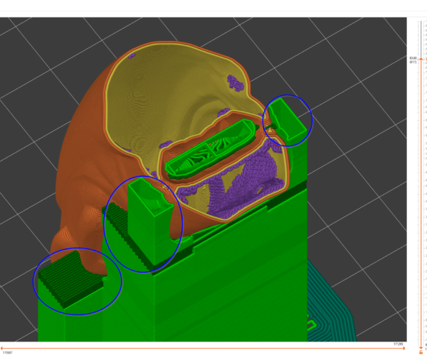
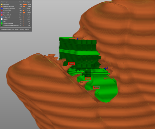
First of all, slicer starts printing the highlighted part on the air (at layer ~590), supports are enabled everywhere: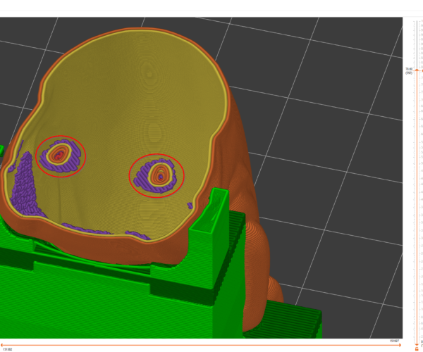
Also I wonder how can I cancel the selected supports at the sides, as they are only a waste of plastic. Basically I failed to create a support blocker for that as it seems that PrusaSlicer requires that the support starts from print table. Any idea?
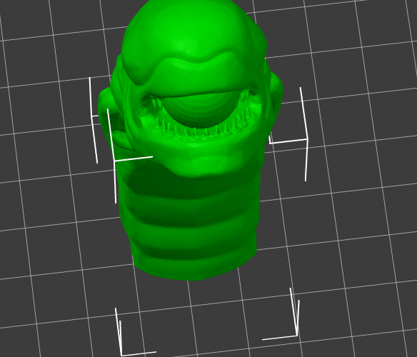
The model was downloaded from here and 3MF project is attached.
Thanks in advance!
Best Answer by Neophyl:
The teeth are barely printable due to some of their size at the extrusion width. Which is why there are extraneous lines. If you add a 0.2 x/y compensation to the whole model you will see the teeth print much better as they become big enough to slice (mostly). Making it a tiny bit larger wont hurt in this instance as it doesn't have to fit to any other part like something mechanical. Once you have confirmed that all the features of the model slice with a slice and preview (without support enabled) you can look into what actually needs supporting by looking for the dark blue sections on the preview. SO its just the upper teeth on this. For this model using paint on support on just the upper teeth makes a big difference. Far more control than an enforcer modifier. Using clipping from below you can easily 'see' the teeth and get to them with the brush.
One reason the support is growing out so much is your pattern spacing, in the version from Sylvia at least (sorry I only downloaded Sylivia's version ) its set to 7mm. This means if it has to grow out it will grow out that much each time. You are better off setting it to something small like 1.5 or even 1mm as that way each time the algorithm has to expand it will go out in smaller increments.
Attached is the 3mf file I used for that.
Infill
You have infill set to 0%. Is there a reason for this? Normally that area you are asking about would be printed on top of the infill. There are several ways to control where the supports get created. You can use paint on supports (you need to be in advanced or expert mode). Or you can use enforcers. See https://help.prusa3d.com/en/article/support-material_1698
Mk3S+,SL1S
To add to Sylvia's post, supports are only for OUTSIDE the model. Infill does the same job INSIDE the object.
Supports and infill
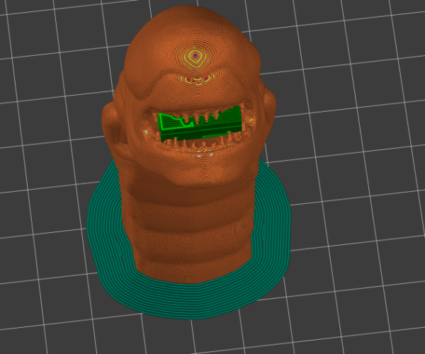
Thanks for your help! Indeed, I need non-zero infill to fix the issue in the 1st image. Thank you for the hint! I wonder if PrusaSlicer generates sort of log to warn the user about such a stupid mistake?
Concerning 2nd image (how to generate only support inside the figure only) I am afraid I did't find anything related in the article. PrusaSlicer want support to touch the table, but I would like to generate the support that starts from the model. Is it possible? Or that does not make sense?
re
Supports are vertical. That is to say that they are created to be perpendicular to the bed. In some cases you might have a support whose bottom rests on a part of the model that sticks out enough to be directly under the support. But your model is not shaped that way. If you want to try the 2.4.0 Beta version, it is better at creating supports in some ways and has an option for 'snug supports', but for this model they will still go down to the bed.
You might be able to print this without any supports. Have you tried? There are just a few small areas of overhang might come out messy but you could probably fix that with sanding.
BTW, the bottom of this model is not flat against the bed and that will cause issues. You can easily fix this by cutting a little sliver off the bottom with the cut tool, selecting keep upper part only.
Mk3S+,SL1S
You might be able to print this without any supports. Have you tried? There are just a few small areas of overhang might come out messy but you could probably fix that with sanding.
The main problem is going to be supporting the teeth; printing them is going to be tricky in any case as they come to very fine points.
BTW, the bottom of this model is not flat against the bed and that will cause issues. You can easily fix this by cutting a little sliver off the bottom with the cut tool, selecting keep upper part only.
This model is not well designed for FDM printing, unless you have the original files to modify I wouldn't bother with this one, there are lots of similar alternatives to try.
Cheerio,
RE: re
I looked at the source of your stl and now I think I get what you are after. The creator of the model said you only need support inside the mouth. I added a support enforcer sphere inside the mouth and tinkered with its placement in the mouth and I got it to only make supports in the mouth. It is fiddly, tho. Making the sphere too big or too far forward will make the supports go down to the bed. I'm attaching my best result. It only supports the upper row of teeth. But maybe you can fiddle with it and get it exactly where you want.
There are several options for shapes of support enforcers and then for supports you select 'enforcers only'.
Mk3S+,SL1S
Supports and infill
Diem, you're right saying that it would be easier to choose a simpler model, but this way there are no challenges and one cannot learn something new.
sylviatrilling, thanks a lot for your example! I see that the support enforcer needs a carefully positioned box/sphere, as once I try to enlarge/move it a bit, slicer starts generating supports from table. So if PrushaSlicer could detect that supports are not interconnected and those which are built from table play no role, it would save our time trying to nano-position the inner support enforcer.
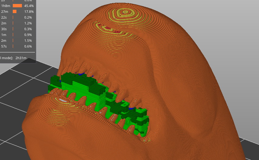
Also, have you noticed that some short external perimeters are hanging in the air?
Indeed
I was just about to post about that very thing. It looks like your dimension of 4 inches tall is too small to print the lower teeth well and that is why you get bits hanging in the air. Some of the teeth have lost their conical shape. What you see is what you get, as far as lines of extrusion. I tried increasing the height to 6 inches and the lower teeth will work much better at that size.
Mk3S+,SL1S
The teeth are barely printable due to some of their size at the extrusion width. Which is why there are extraneous lines. If you add a 0.2 x/y compensation to the whole model you will see the teeth print much better as they become big enough to slice (mostly). Making it a tiny bit larger wont hurt in this instance as it doesn't have to fit to any other part like something mechanical. Once you have confirmed that all the features of the model slice with a slice and preview (without support enabled) you can look into what actually needs supporting by looking for the dark blue sections on the preview. SO its just the upper teeth on this. For this model using paint on support on just the upper teeth makes a big difference. Far more control than an enforcer modifier. Using clipping from below you can easily 'see' the teeth and get to them with the brush.
One reason the support is growing out so much is your pattern spacing, in the version from Sylvia at least (sorry I only downloaded Sylivia's version ) its set to 7mm. This means if it has to grow out it will grow out that much each time. You are better off setting it to something small like 1.5 or even 1mm as that way each time the algorithm has to expand it will go out in smaller increments.
Attached is the 3mf file I used for that.
re
@Neophyl, how do you do an 0.2 x/y compensation?
Mk3S+,SL1S
Print settings>Advanced>Slicing> XY Size Compensation. Its the settings above elephants foot and has been in the software since before it was called Prusa Slicer. Its very useful as an alternative to messing around with extrusion widths or the buggy detect thin walls for 'artistic' or no size critical models where you cant adjust things easily in CAD.
Also more people should really know the search function built into PS now. The dev team spent considerable time adding it and its one of the MOST useful but often overlooked features as you can just search for settings. It should be one of the first things communicated to users.
Supports and infill
That you all for you help. "XY Size Compensation" did it's job. It also works for value 0.1 mm, or do you suggest to set it equal to nozzle diameter?
With x/y compensation I usually start small and work up. I tried 0.1 and that still left a few bits, so increased it to 0.2 to make the teeth a little thicker which I think will help them not break away when removing the support. I've never had to go up to anything near the extrusion thickness. Remember that you are moving all your perimeters outwards. So if you have a wall between 2 points that was 0.4mm to start with then adding 0.2 will actually make the wall 0.8.
