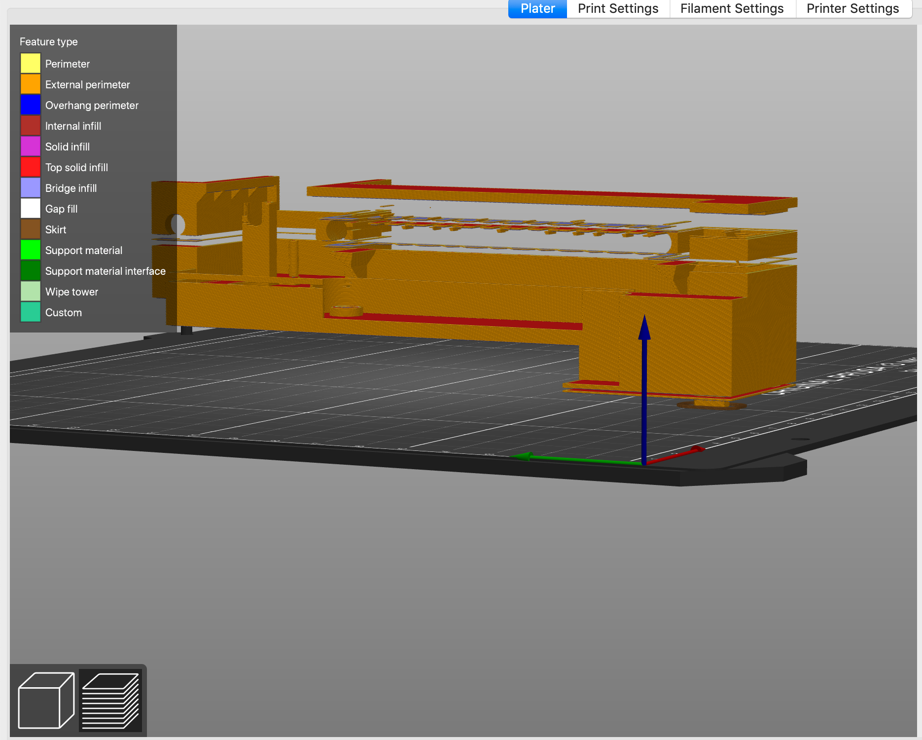
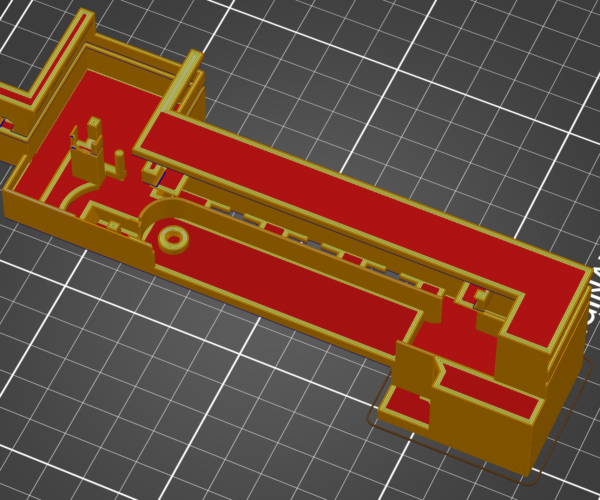
Gap appearing in the model once sliced
Hi, I am trying to print something at 45 degrees but when I slice it, it creates a gap as shown in screenshot. Help!
RE: Gap appearing in the model once sliced
There should be a fix with netfab option in the menu when you right click on the object... try that.
I try to make safe suggestions,You should understand the context and ensure you are happy that they are safe before attempting to apply my suggestions, what you do, is YOUR responsibility.Location Halifax UK
RE: Gap appearing in the model once sliced
Joan it seems this post is on twice with this one being much delayed.
RE: Gap appearing in the model once sliced
I am having the same problem, only worse - and one more. My object is complicated, consisting of a housing with two motors sticking out the bottom, one at the plate level, and one 17mm above the plate. I use a blocker to stop supports above the base line of the object. The pic below is a bottom view.
I have printed this object many times, but occasionally it puts big horizontal gaps in the slice code.
Then there is another problem. The motor holes are completely filled in. I have gone through many, many cycles trying to get past these problems. I have loaded different versions that sliced coeerctly in the past. I have re-exported the image from CAD into .stl. I have had PS repair the .stl file, then import it back as an .obj with the same results. It appears this is a PS problem.
RE: Gap appearing in the model once sliced
Why not post the stl file and /or the .3mf project file and possibly get another set of eyes on it ? Unless its a propriety model of course. Without the model or project theres not a lot anyone can do to help.
If you don't mind me asking what CAD software was used to generate the model ?
RE: Gap appearing in the model once sliced
Be glad to post files. The CAD is Vectorworks, version 2020. I do all my slicing from .stl files. Note, I haven’t included the blocker .stl, since it doesn’t make any difference to the outcome. I also don’t see the .stl file I attached, so I will try again.
RE: Gap appearing in the model once sliced
I have tried twice to use the Attach File / Choose File below. I select the .stl file and it appears to load, but it doesn’t show up in the window.
Any suggestions? I am trying a third time.
Edit:
Didn’t work. If I simply drag and drop it on the window, I get an error message saying this type of file can’t be loaded for security reasons????
RE: Gap appearing in the model once sliced
@ben-g16
You need to add files to a zip archive for the forum to accept them. except for jpg/png files.
RE: Gap appearing in the model once sliced
OK, let’s try this again. Zip file prepared. Don't see that instruction anywhere. Edit: OK, I see it got through. Maybe the file size was the killer. Original file was 24MB, zip was 2.9MB. Would be nice to have an alert for oversize.
RE: Gap appearing in the model once sliced
@ben-g16
Wow, that's quite possibly the most broken stl file I have come across. Imported it into Blender and it was obvious that its broken as I'd say about 50% of the faces are missing and you can see through large parts of it. If you run the 3d print tool on it it reports the following
44604 Non Manifold Edges
1357 Non Contiguous Edges
18832 Intersecting Faces
976 Zero Faces
188 Thin Faces
I also a tool called 3D-Tool to preview stl files and that renders it with the same faces missing too.
I'm not surprised when anything tries to fix it large parts get filled in. Its just really really broken.
This is what it looks like when imported in (thats the solid render not a wireframe view)
RE: Gap appearing in the model once sliced
@neophyl
Thanks for your review. I am printing a previous version that made it through the conversions process. I actually redrew this object about a month ago because of printing problems. It too days to redraw in a straight shot without any “corrections". So, the big question is - is there any way to fix it?
One of the things I did was an Intersection command that subtracts the object from a surrounding block, supposedly simplifying the internal structure. Another trick is to execute the Convert to Generic Solid command, which can reduce the file size over 10x.
Thanks
RE: Gap appearing in the model once sliced
@ben-g16
I'm not familiar with vectorworks so don't know what options it has. The one I attached to my post was done with Make Manifold button in Blenders 3d print add on (you can see it on the right in the screen grab). I don't know how good a job it did fixing it as you would need to compare it to your original model in vectorworks. But for a single click job I don't think it did too bad.
I did notice that the fixed stl output was considerably smaller in size so that convert to generic solid might be worth a try. Does vectorworks not have any tools for checking if a model is manifold and without intersects etc ?
RE: Gap appearing in the model once sliced
VW is straight CAD, mainly for Architects. I am doing engineering/product design. It will export numerous file types (~26), and has the internal Generic Solid command, which I use frequently to reduce files from 500MB to 20MB or less. I use other commands as crutches to fix files, which sometimes works. There are no commands that indicate the internal structure of a file.
When internal structure is messed up and it won't do a command, such as Push/Pull (a surface), or fillet or chamfer, it simply says “fix the geometry”, which is no help. The only real check I have is to look at the wireframe model and see if there are hidden lines indicating surfaces that aren't joined correctly.
I tried the PS "Repair .stl file" command, and ran the .obj file that resulted, but got the same result. I am continually upgrading/fixing my files with new features or improvements for function or printing, and I have completly redrawn this one several times. It is supposed to be OK, but I guess not.
RE: Gap appearing in the model once sliced
I have previous used the STEP format as an intermediate format to fix problems in CAD programs. Maybe a export from vectorworks to STEP and re-import of the STEP file will remove/fix unwanted extra geometry before export to STL.
Alternatively vektorworks -> export STEP -> import into FreeCAD -> export STL.
FreeCAD is as the name implies free, but Fusion 360 will be good too (also free).
The main goal is to keep the solid parts and make the STL file from them.
Have a look at my models on Printables.com 😉


