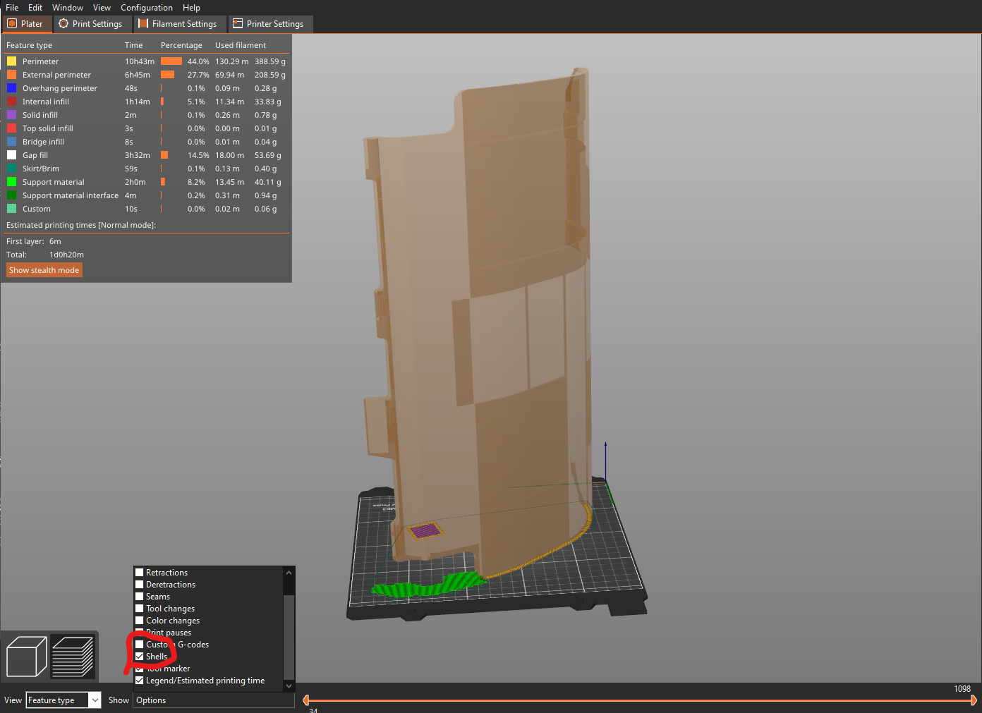
Display option "Shells" looks strange
As you can see I have enabled the display to show only "Shells". To me the pattern seems so strange. Is there an error in the STL or is the display normal? (Light / Dark brown differences)
Because I have bad contours in the dark brown areas....
Best Answer by Swiss_Cheese:
@giulio-2
The shell view appears normal, meaning what you would expect from Prusaslicer shell view the model sliced fine and no errors where detected.
Enjoy
Swiss_Cheese
RE: Display option "Shells" looks strange
Without at least the model but preferably the project file its impossible to say if its a model issue. However I would say its most likely due to the way the model is constructed.
In Prusa Slicer, load your model just like you have it pictured and then go to file, use Save Project As to save a .3mf file. The 3mf will contain the model(s) as well as the profiles you have selected as well as anything else like modifiers etc. Take the 3mf and then zip it up. The attach it to a post here. It must be zipped or the forum wont allow the attachment.
With a project we should be able to get identical results so its the best way of debugging issues.
RE: Display option "Shells" looks strange
Thanks Neophyl for your quick reply! Here you can find the .3mf file:
RE: Display option "Shells" looks strange
@giulio-2
The shell view appears normal, meaning what you would expect from Prusaslicer shell view the model sliced fine and no errors where detected.
Enjoy
Swiss_Cheese
The Filament Whisperer
RE: Display option "Shells" looks strange
Okay, that means I can generally rely on it, if no errors are found before slicing (e.g. open edges), that everything is fine with the STL?
RE: Display option "Shells" looks strange
I did take a look at the stl in Blender. On the whole its a quite well constructed mesh. There is only one open non manifold edge and thats at the 'chisel tip' of your built in support. I think if you altered that built in support slightly you could remove the need for the overhang where it connects to the part needing its own support. This would simplify printing somewhat.
I didn't take too long a look at the settings in the 3mf but I would say your support settings are also not optimal. First change I would make is from grid to type Snug, and set the expansion down to 0mm. I've attached a updated 3mf file so you can see the difference easily just a few minor changes make.
You might also want to look into using the 'highlight overhang by angle' slider on the support paint tool too.
RE: Display option "Shells" looks strange
@swiss_cheese
I think your answer is short and to the point the most important for this general question, thanks!
@neophyl
Thank you for viewing and dealing with this .3mf file. I find the support structure settings from you very interesting and much more economical. What is your experience with these settings? Does the support material remove well? Are the supports sufficient in stability?
RE: Display option "Shells" looks strange
I don't normally use a .6 nozzle on my Mk3 (that's usually reserved for my CR10S). Snug supports is by far the best option. I haven't found a circumstance as yet where it isn't. For the rest supports on my mk3 remove easily and cleanly. I find that using 4 top interface layers means that they bind together alot more, this makes removal easier as they tend to come away in one piece. When using 2 they can breakup so you get patches left stuck to the part sometimes.
The other settings I will vary around depending on the part. For example support spacing can be changed as the interface layers at 4 will still bridge it, so you can adjust the spacing wider for larger flat areas. Contact z distance I used to use 0.2 as is widely recommended (0.2-0.25) but from recent testing with snug supports and using PLA I've found that even 0.1 generally releases cleanly, where before it wouldn't. That seems to depend on the material though so as usual if you find that supports stick too much then tweak it out towards 0.25mm contact z distance.
For me the key settings are Snug and 4 top interface layers. I also usually set bottom interface layers to 0 if the supports start on a part which I didn't remember to do on the project I linked. I've saved my own profiles so I normally don't have to change that.
RE: Display option "Shells" looks strange
Thanks for the detailed description, your settings sound very interesting.
The support with your .3mf file went very well and was also very cleanly printed. Thanks for your help!