Air filtration fan FAN3 on the xBuddyExtension board
Hey everyone! I've had my Core One L for a week now, and everything is awesome so far 😊
My next step is to connect the chamber exhaust to a custom air filtration setup. The exact details of that are not relevant, so I'm skipping over them for now. However I do have some questions with regards to xBuddy / xBuddyExtension electronics and software logic, which will be of interest for a lot of others that go into similar directions, I think. Here are my questions, numbered for easier referencing:
1 Electrical questions:
- 1.1 The original "Intel CPU cooler spec" https://glkinst.com/cables/cable_pics/4_Wire_PWM_Spec.pdf says the mainboard should have a pull up to 12V on the tacho signal. From https://www.prusa3d.com/downloads/Electronics_drawings/MK4-xBuddyExtension-06.pdf (page 12) I get the tacho signal is pulled high to 3.3V on the xBuddyExtension board, with a protection (BAT54KFILM) against external pull-ups to higher voltages, correct?
- 1.2 The xBuddyExtension schematics show a https://assets.nexperia.com/documents/data-sheet/BUK6D120-40E.pdf 3A capable FET as the high-side switch on the 24V line to FAN3 (EXT_POWER_FAN). What is roughly the max safe, continues current draw, during printer operation, on the FAN3 connector? So I can decide if I need an extra PSU for my solution, or if I can pull the power from the xBuddyExtension board.
2 Logic / software questions: I have not tried / used the air filter on the Core One (L) before.
- 2.1 Are the chamber fans logically linked to the air filtration fans? I.e. if the chamber fans run, then the air filter fans run as well.
- 2.2 If >yes< how is the link done? I.e. same set RPM maybe?
- 2.3 If >no< what is the general idea on how a user should set this up? I.e. fixed air filter RPM for the entire print, or custom G-Code, etc.
- 2.4 If the RPM on FAN3 is set to 0, will the 24V output on the connector be shut off?
I did some searching through the forum and couldn't find something on the above, but I probably just didn't put in the right searches 🙃
Anyways thanks to Prusa for a great printer, and any answer in advance!
RE:
Update on my question 1.2: I had a closer look at the MK4-xBuddyExtension-06.pdf schematic. There is a TPS16630RGER which is a configurable current/power fuse, with current measurement capabilities. If I followed the datasheet correctly, the xBuddyExtension has this configured to about 4.6A max, and its on the 24v rail. So this places an upper current limit on the entire board (5V and 3.3V on the board is derived from the 24V rail). This chip also offers a measurement output of the current going through it ("IMON" pin), which goes into the STM32 uC, that reports back to the main (xBuddy) board, that eventually shows this on the front LCD (under sensors).
So what is connected to the xBuddyExtension board:
- Chamber fans (these are 24V directly, and draw about 600mA on 100%).
- RGB led strip for lighting (about 100~200mA on 100%).
- MMU (don't have one, can't test).
- One other fan (not sure what that is).
- USB power delivery (not sure what that is for)
The current displayed in the UI also includes the print head heater, but its not connected to the xBuddyExtension from what I can tell. So I assume the displayed value adds in other sources. For me it idles around 0.5A with nothing running, and lights dimmed. This sounds a bit much for just the STM32 uC and assorted bus drivers and such, which again points at more things being summarized into this one value.
So from this I guess that an about 1A draw for FAN3 should be in budget, depending on what else you connect, maybe even more (or less with MMU attached) ... Hope someone from Prusa can confirm this ballpark estimation 😋
RE:
This post shows the fan that Prusa drives on Fan3. Alveo3d lists a similar one, BLHP2432-H24, at ~24W at 24V. To quote @_kaszpir 's good advice,
"Of course this needs additional confirmation, so for now you fry the hardware on our own." It looks like you're doing a good job on the research, keep us posted on the project.
RE: Air filtration fan FAN3 on the xBuddyExtension board
@ssmith Oh cool thanks for pointing this out! 24V 4pin PWM fans are rare, I just bought one of those to test 😆
I also now had a look at the Molex connectors used (151350403) and those have a max of 2A per contact. This gives a reasonable upper limit for the FAN3 connector I think. Some confirmation from Prusa would be nice, but I guess this mostly covers Q1.2 for me 🙃
Will keep you posted about more findings 👍
RE: Air filtration fan FAN3 on the xBuddyExtension board
I have seen posts indicating the Prusa fan is 24v 0.5A and the max is 1.0A, but no true source.
From my understanding, when you enable the menu setting for the advanced filtration.
"Note: When enabled, the Advanced Filtration System also takes over chamber temperature control and disables the cooling fans (with the exception of critical overheat situations)."
As of 6.4, you can now control the chamber fans with G code
M147 (Set): Explicitly marks the current print as requiring chamber filtration, overriding the automatic behavior based on the filament parameters.
M148 (Unset): Explicitly disables chamber filtration for the current print.
Firmware 6.3.1 added the DIY fan option, detailed here
RE: Air filtration fan FAN3 on the xBuddyExtension board
Take a look at issues in the prusa-buddy-firmware repository, search for "fan3". Comments in those issues might be interesting or helpful.
RE: Air filtration fan FAN3 on the xBuddyExtension board
...missed the edit timeout...
For instance that's where the information about the .5A / 1A current draw comes from.
RE: Air filtration fan FAN3 on the xBuddyExtension board
Thanks for the many replies!
I went over the release note linked above, and I can't fully picture it yet ... But from what I read there in case you have the official filter installed, the filter fan takes over for the camber fans. So the same feedback loop over temperature applies, I guess, its just purely doing it with the filter fan...? For the DIY solution its seems that the logic is to just map the "filter fan" to chamber fan. So DIY = no fan3 basically. I have to think about it a bit more on how to hook up what I'm building and how make it practical.
The find on the github issue is an interesting data point. I will soon have a look at the board and follow the traces a bit to match them to the schematics. This should give more insights on whether the 1~2A range is doable. Also maybe I'll look for "FAN3" things on github issues, as @ssmith suggested.
On that note the Alevo3D BLHP2432-H24 arrived yesterday, and I took it for a quick spin to measure some real world values. According to its datasheet it is rated for 1A with 1.1A max. My no-load test (lying flat, plenty of room around it) measured it at a constant 1.4A at 24V, so about 30% above the expected "max" draw. At this level it was doing about 4000 RPM so this at least did match the data sheet. Also according to the data sheet the tacho and PWM signals are supposed to be 5V, but everything works just fine with 3.3V. The PWM input could do 1% duty cycle as well, which is great for feedback control.
There's some more parts in the mail, which hopefully arrive before the XMas break. Will keep you updated what I find 😊
RE:
you could also use fan control signal to trigger other devices via optocouplers.
I was thinking about directly integrating some features into the printer, but I resigned from it and switched to HomeAssistant integration (via PrusaLink) and then trigger automation based on HA. This way I do not need to draw power from the printer itself but from the other devices around it - independent PSU, fans, led lights, esp32+camera, esphome, some i2c sensors and so on.
See my GitHub and printables.com for some 3d stuff that you may like.
RE: Air filtration fan FAN3 on the xBuddyExtension board
Hey!
Have also been trying to make a custom filtration as original seems to be more restrictive and thought that this could lead to C1 sounding like aircraft on the runway while printing PLA 🙂
Have been searching all over internet about original fan specs and board fan3 header limits without luck, well found only that original fan is 0.5 amps rated and AI saying board should be max 1 amp rated (dreaming? Or maybe got info from same github issue).
Also had doubts of buying Alveo3d fan or XL enclosure fan (also no specs there). So while I was in doubt I have stumbled on 12032 fan on aliexpress (24v and rated for 0.5amps) and pulled the trigger.
It’s been sitting for some time already as I had other things to do, but today I finally hooked it to the fa3 header and gave a spin. At least for a couple minutes test run nothing blew and I was able to PWM it through settings menu (will be continuing my filter enclosure now to hook it in place)
so if you are searching for alternatives check on ali for “blurols 12032”. It comes with clickmate connector
RE: Air filtration fan FAN3 on the xBuddyExtension board
Back from XMas break, hope you all had a good time 🙂
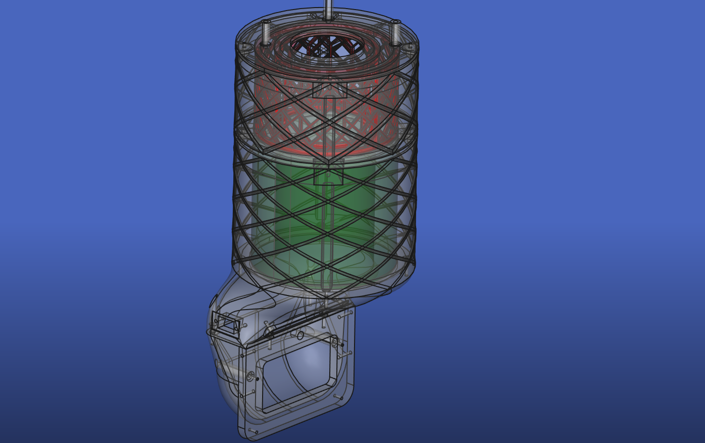
The remaining parts arrived, I finished the CAD and printed all the parts. The design is built around an "FY0611/30" filter (green in the CAD), which originally is for the "Philips Air Purifier AC0650 AC0651" models. I chose this as is seems to have plenty of area, was convenient in size, and lots of easy to source replacements are available. This covers the HEPA / particle filter section. The VOC part is done with a second stage activated carbon filter (red in the CAD). This is designed to be filled with standard loose pellets, which are really cheap compared to mats, and more effective. The Alevo3D BLHP2432-H24 is mounted at the very top, pulling air through the stack.
The assembly was pretty easy:
- print all the parts (lower 2 parts should be PETG for heat and flex, rest can be PLA)
- put in heat-set inserts for screws
- pad HEPA filter with insulation foam, to create a seal (local hardware store should have plenty of options in the heating / plumbing section)
- glue an "insect window mesh" to the printed pellet filter supports, glue both of them down to the mid3 section, add some foam padding to the top of the two meshs to seal against top plate
- fill in pellets
- add more foam to seal top fan intake
- screw all the parts together and wire up Alevo3D BLHP2432-H24 to FAN3 connector on extension board
Then I did some quick tests to see if anything got hot: 100% speed on FAN3 and 100% speed on chamber fans. Let this run for a couple minutes and checked the mosfets on the board -> everything was quite cool, so this should be fine even under full tilt. The Alevo3D fan is rather on the louder side, about the same as the chamber fans on 100%. Judging by the suction (with closed chamber, air vents open, chamber fans off), it seems that it has way more power than needed. In fact the chamber fans start spinning at 800 RPM just from the suction through the filter 🤣

Next I did a quick PETG test print, setting the filtration to "Advanced filtration", and "Filter all materials", min fan speed 10% . This seems to work like the change log suggests: the chamber fans are off and the temperature regulation is done with FAN3. From this one test however I had the feeling that it was running the FAN3 quite a bit harder than it would need to, (mentally) comparing the air throughput to the chamber-fans-only setup I previously had. This would make sense as the stock "Advanced filtration" fan is probably quite a bit less powerful than the 30W Alevo3D one.
Will run more prints in the coming days, and come back with more info.