Further information on Basic Board and PSU for Original Prusa Enclosure (for Filtration unit and *custom* LED)
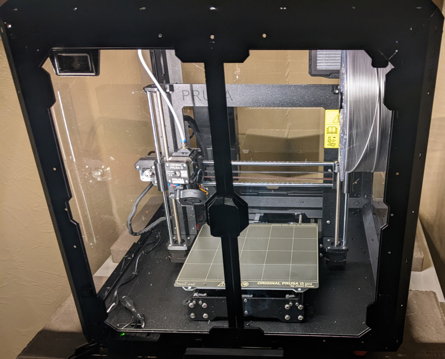
I bought the enclosure with the filtration system.
After the regular setup I added the Hinged Lid (add-on) and combined it with my existing LED illumination based on the Dual MMU2 Light - 24V - Model
The Enclosure Basic Board already has a connector for LEDs (in order to be used with White LED strip (add-on).
However, I thought I could use it to switch my own lighting, but I could not find any technical information (neither LED strip nor board).
Maybe someone can help me with my questions:
- Is there any information about the Enclosure Basic Board (like circuit diagrams)?
- Does it provide 24V at the LED output?
- What type of connector does the board use? (I looked at a few JST Wire-to-Board Connectors but could not see for sure the right one)
It's no problem to connect my LEDs to the PSU as before, but it would be cool to use the existing switch on the Enclosure Basic Board right away.
Thanks in advance for information and your support! 🙂
RE: Further information on Basic Board and PSU for Original Prusa Enclosure (for Filtration unit and *custom* LED)
I am also curious of this, and want to know what the extension plug is for. Any kind of data sheet for the basic board would be helpful!
RE: Further information on Basic Board and PSU for Original Prusa Enclosure (for Filtration unit and *custom* LED)

RE: Further information on Basic Board and PSU for Original Prusa Enclosure (for Filtration unit and *custom* LED)
Then why is there an OPEN HARDWARE logo printed on the pcb?
RE: Further information on Basic Board and PSU for Original Prusa Enclosure (for Filtration unit and *custom* LED)
I've been trying to figure out the basic board we have for our filter accessory, I haven't figured out the particular connector brand/model but the pinout on the board from left to right (silkscreen text "right side up", power connector bottom left, LED / FAN / EXTENSION connectors bottom right), for the LED connector appears to be 24V, switched ground (when you press the button to turn on the lights), and then three no connects.
I say no connect because looking closely at the board (and testing with multimeter) it seems the other three traces go to R9, R22, and R24 just above that connector, but at least on mine nothing is installed there. The other side of all three of those indicated resistors is a shared ground plane with the switched ground on the LED connector, so even if they were installed, they'd just be jumpering the presumably RGB channels to the on/off switched ground, maybe reducing combined intensity, so only providing a way to use an RGB strip as a bad "white" strip ? That switched ground plane appears to be connected to the drain2 of the FW297 just above it, I would guess that the drain1 on FW297 goes to the FAN header but I didn't check it. Since I don't see any microcontroller looking chips I am assuming half that mess of resistors, caps, and transistors in the top right area is some kind of toggle-able on/off circuitry toggled by the momentary (probably?) switches S1 and S2 for LED and FAN control.
With no apparent connection from the LED header to anything else for color control, and so few connections on the EXTENSION header, and no micros I can find, I am going to guess the "Smart Box" will replace the "basic board" assembly either in part (reusing the enclosure) or entirely (new enclosure for it too), rather than somehow plugging into the EXTENSION header to augment it.
If we can figure out what the header connector type is for these LED / FAN / EXTENSION headers then it should be trivial to wire up some 24V LED strips of our own (and as many as we desire, where we desire) instead of shelling out $60 shipped to get a single white LED strip from Prusa ... if not, well, there's always the option of soldering something else to those two pins that are actually used ...
RE:
Apparently I should have just waited a few more minutes to post, I think I finally found the right connector type.
I got caught up thinking "JST connector" and didn't originally look beyond that, but it's a Molex CLIK-MATE connector, looks like. I'm not 100% sure if it's the 1.25mm or 1.5mm pitch one, didn't think to whip out the caliper on the board and I've already reinstalled it... but comparing the pictures on digikey and mouser, it looks like 1.5mm (the PCB surface mount housings are slightly different, looks like 1.5mm). Which is nice because then you can just order up a pre-terminated wire harness with CLIK-MATE connector on the end (Molex 0151350503 https://mou.sr/3ZpvDpv )...
I'm going to order one up and see if it fits when it gets here. Just over $10 shipped to me, if it's wrong then it's not much to waste on the try.
RE:
yes, the connectors seem to be clik-mate, although the terminals are a bit different: https://forum.prusa3d.com/forum/project-oni-general-discussion-announcements-and-releases/basic-board-connectors/#post-623810
RE: Further information on Basic Board and PSU for Original Prusa Enclosure (for Filtration unit and *custom* LED)
Well I can confirm the pre-terminated CLIK-MATE wire I ordered off Mouser worked fine. Chopped it in half (it's terminated on both ends), wired up the +24V and GND wires, and slapped some leftover 12V LED strips in so that they were wired in serial to run at 24V.

Wired up like so : https://www.waveformlighting.com/pcb-designs/using-a-12v-led-strip-in-a-24v-system
RE: Further information on Basic Board and PSU for Original Prusa Enclosure (for Filtration unit and *custom* LED)
Has someone checked the pinout of the FAN/Filtration Plug? What other than VCC and GND could it need? It is only on/off without speed regulation.
I am considering to skip the basic board and switch the addons via GPIO pins of my Octopi, since there is no information on the smart box/extension port yet.
RE:
 Hi,
Hi,
I wanted to add my 12V Led bar and found a way todo this by adding it to the output of the White Led strip.
Not my best soldering job but it works!
using an LM2596 to convert to 12V and only add very little load, not sure how much amp the base board supports but a few more 12V leds work just fine.
RE: Further information on Basic Board and PSU for Original Prusa Enclosure (for Filtration unit and *custom* LED)
Hi,
curious about the additional "EXTENSION" connector on the Basic Board, I took some time and a magnifier with the intention to identify as much of the board's circuit as possible.
I am not sure I got every connection right. Hence, treat my results with caution!

In the attached image:
- purple squares/circle: components on the board
- filled red: associated with power supply (a 2A fuse, and a ton of capacitors, likely for denoise and overcurrent protection)
- filled brown: FAN circuit
- filled blue: LED circuit
- connections (lines, dashed lines run on the back side of the circuit board)
- red: 24 V (Vcc)
- green: Ground
- light blue: LED
- yellow: FAN
While I did not look up all the components, nor did I measure resistor values, I can still make some assumptions on how this board works:
- The main chip (below the FAN button) is a Power Mosfet Dual N-Channel chip
- According to the linked datasheet, it is rated for up to 4.5 A, which exceeds the fuse's value of 2 A
- Two (linked) channles are used to switch the LED, the other (linked) two channels switch the FAN. Both on the GND side
- Two of the "EXTENSION" connector's pins are connected to these outputs.
- The circuits for the LED and FAN appear to be identical, consisting of two additional transistors (unknown type), several resistors, status LED and some capacitors (likely for denoise). I did not check the values, but the parts look fairly identical
With the little knowledge I have about electronic circuits, I think it works roughly as follows: The main chip either opens or closes the GND connection for the LED and FAN. Since each circuit has two additional transistors (of unknown type), I think this is the logic for a self-sustaining switch based on the latch button.
So what does this mean for modifications?
- As the MOSFET chip is rated for up to 4.5 A, whereas the fuse seems to limit to 2 A, this is likely the bottleneck to adhere to. The current could also be limited by thin connections, yet I doubt they would design a Board with a 2 A fuse where the connections are designed for less.
- As already pointed out, only two of the 5 LED connector pins are actually used. In addition, the circuit for FAN and LED seems pretty much identical. Hence, the FAN connector could also be used for driving some 24 V LEDs.
- The "EXTENSION" connector merely mirrors the switched GND connection of FAN and LED. Hence, it could also be repurposed.
As far as I can tell, the connections are as follows (from left to right):
- LED
- 1: 24 V
- 2: GND (switched)
- 3: not connected
- 4: not connected
- 5: not connected
- FAN
- Disclaimer: As far as I know, a 4 wire FAN connector usually consists of Vcc, GND, a Sensor line (for speed reading) and a PWM line for setting the speed. The latter two are, two the best of my knowledge, only connected via 2 capacitors to ground, which basically renders them useless.
- 1: GND (switched)
- 2: 24 V
- 3: capacitor to GND
- 4: capacitor to GND
- EXTENSION
- 1: GND
- 2: 24 V
- 3: GND (switched by FAN button)
- 4: GND (switched by LED button)
Originally, I was hoping that the EXTENSION connector might allow for adding external switching (e.g. by a RaspberryPi). Unfortunately, as far as I can tell, this is not the case. Yet it might facilitate to add additional LEDs by using the EXTENSION connector.
RE: Further information on Basic Board and PSU for Original Prusa Enclosure (for Filtration unit and *custom* LED)
A quick update:
I connected the original LED strip to my lab power supply measuring the current consumption. It draws 0.18 A so well below the 2 A threshold.

Furthermore, I used the EXTENSION connector to connect an additional custom 24V LED strip between the 2nd (+) and 4th (-) pin (counting from left). As expected, now both LED strips (original and custom) are being switched by the LED button.

Here's my very well lit enclosure 🙂

RE: Further information on Basic Board and PSU for Original Prusa Enclosure (for Filtration unit and *custom* LED)
> It draws 0.18 A
that low? so how many leds are there? 20?
See my GitHub and printables.com for some 3d stuff that you may like.
RE: Further information on Basic Board and PSU for Original Prusa Enclosure (for Filtration unit and *custom* LED)
I just set up an ESP-32 camera that updates PrusaConnect every 5 seconds. I used a 24v - 5v buck converter with a USB socket, and a 4-pin molex plug to attach to the extension port on the basic board. This works really well, as the camera turns on and off with the light strip, but I'm looking for a way to power up the lights/camera automatically when the printer turns on.
Has anyone figured this out?
Thanks!
RE: Further information on Basic Board and PSU for Original Prusa Enclosure (for Filtration unit and *custom* LED)
Thank you for the board analysis and measurement data.
I't clear to me, that you know way more about electronics than you let on...
It is obvious, that the "smart box" will replace this little board.
(IF- or When it is released)
But the love of my wife, I can't figure out why Prusa have made a custom LED board and not just use some run-of-the-mill LED strip - maybe with some mounting hardware...
The more I read about this current solution, the less I like it and the more overpriced I find it.
Did I miss anything?
RE: Further information on Basic Board and PSU for Original Prusa Enclosure (for Filtration unit and *custom* LED)
What connector can I use to run an extension for the Prusa LED?
RE: Further information on Basic Board and PSU for Original Prusa Enclosure (for Filtration unit and *custom* LED)
See my GitHub and printables.com for some 3d stuff that you may like.
RE:
Anyone knows more about the FAN?
From what I have found:
- fan https://help.prusa3d.com/guide/advanced-filtration-system-add-on_722025 provides link to an image with a fan details ALVEO3D BLHP2432-H20 which is a DV24V 0.5A fan 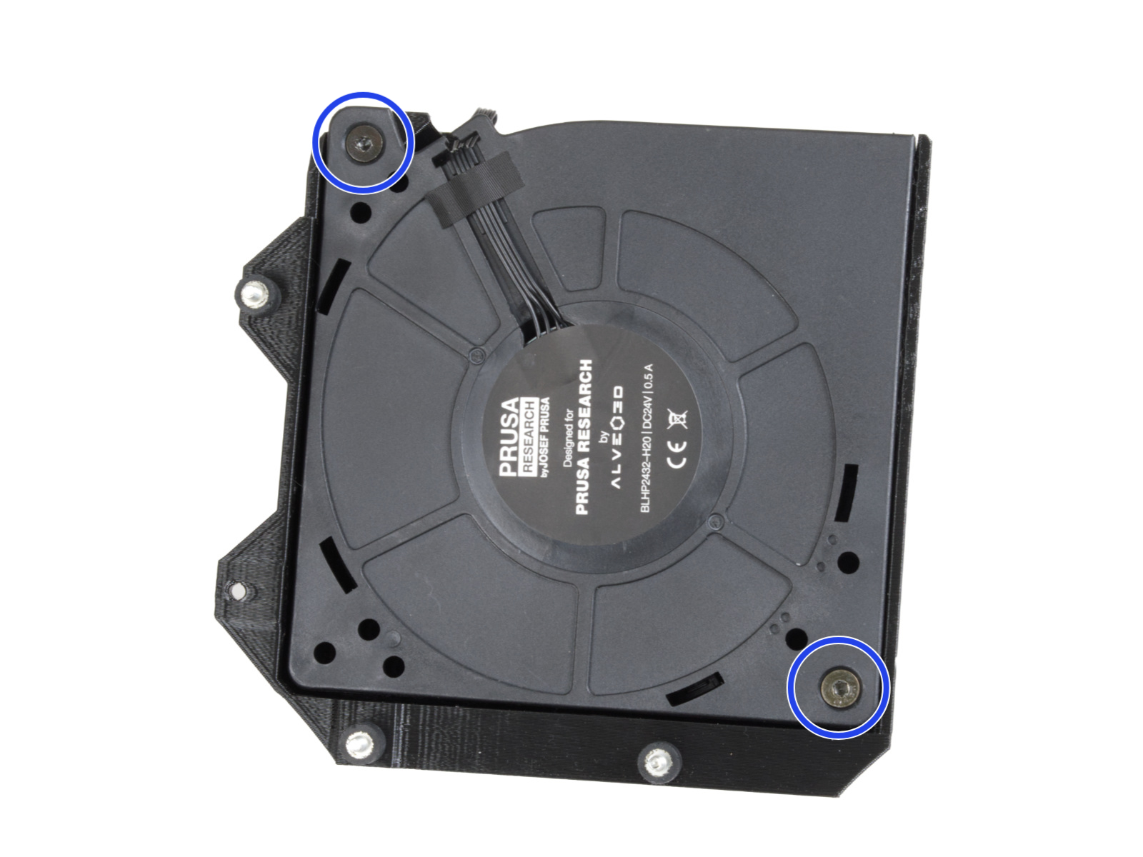
We can see 4 wires on the fan cable.
looking at the Alvero3d site we can find https://www.alveo3d.com/wp-content/uploads/2020/05/2020_manual_1.3_en.pdf (or image of some of the electronics they do
which shows that one pin is indeed PWM.
Of course this needs additional confirmation, so for now you fry the hardware on our own.
See my GitHub and printables.com for some 3d stuff that you may like.
RE: Further information on Basic Board and PSU for Original Prusa Enclosure (for Filtration unit and *custom* LED)
In case anyone finds this thread - Prusa has published the Basic Board schematic: https://www.prusa3d.com/downloads/Electronics_drawings/FDM-MKx-EncosureBasic-09-1.pdf
I was always looking on GitHub for this stuff - the page you need is here: https://www.prusa3d.com/page/open-source-at-prusa-research_236812/
Prusa MK4 since Jan 2024, MK4S/MMU3 since Jan 2025, Printables: @MikeB_1505898