RE: Gantry resonant mode and VFA artifacts
But today there are good optical systems (think computer mouse). Additionally, an accelerometer on the head, plus some sensor fusion algorithm.
Good point; measuring with the required resolution should certainly be achievable. But for 3D printing, would you really want a positioning system where you accept random slippage of the drive and compensate it via closed-loop control? Not all components in the system respond quickly, especially the filament flow will lag behind somewhat when the XY speed fluctuates, I'd assume.
It's clearly technologically more advanced but I wouldn't say it can't be done and perform better than conventional open-loop steppers.
After all, the loop needs to correct only for belt slippage, otherwise it's the same as a conventional system. The high-frequency information comes from the accelerometer, is combined with low-frequency / static information from the optical sensor. Algorithms in that area are well understood e.g. used in GPS and friends, "Wiener filter" comes to mind.
Or put a 2nd actuator level e.g. solenoids or piezo on the print head to act directly on the accelerometer feedback minus known intended movement. Looks simple on paper 🙂
RE: Gantry resonant mode and VFA artifacts
Do you think the "waves" on the measured vibration match the VFA? Probably hard to say..
But on the Z axis they do seem to be torsional since they are very aligned on the alternating pattern. Even o X they alternate a bit.
Could it have to do with the bearings on the rails? I don't think so, since they should be smooth unless there were defective balls in it.
PS: Please don't take this in the wrong way, but it would be nice to keep this thread on topic! It is nice to read on the ideas of an alternative to the CoreXY system and on software mitigation strategies, but maybe in a separate thread 😀
Lets not derail it from the great work that @huggypanda is doing!
RE: Gantry resonant mode and VFA artifacts
You're absolutely right, I didn't mean to belittle his work. He does a great job. @huggypanda: At what print speed was the graph measured?
RE: Gantry resonant mode and VFA artifacts
It's only good work if it fixes the issue and so far I have not. 🙂 Already had one false start and no good answers. I wish it was as simple as belt tension for my setup but it just hasn't fixed it or really even improved it.
The print speed was 90mm/s and horizontal motion (left to right). That's just my most problematic speed. I'm sure everyone's a bit different.
You're absolutely right, I didn't mean to belittle his work. He does a great job. @huggypanda: At what print speed was the graph measured?
RE: Gantry resonant mode and VFA artifacts
When I look at those pictures on page 1, the VFAs seem to change amplitude suddenly at discrete heights. Most VFAs on my printer run the entire height of the part, save for about 3 mm near the build plate that's glossier. Does that vertical spacing correspond to anything?
RE: Gantry resonant mode and VFA artifacts
As for controlling the movement and position of the print head, just look at how it is solved in ordinary computer printers. Old types of dot matrix printers were actually controlled by stepper motors in both directions (print head position (X axis) and paper movement (Y axis)) without feedback. Modern printers (inkjet) are controlled by ordinary DC motors. In the path of movement of the print head (X axis) you will find a transparent strip with a whole series of dark lines and on the head carriage there is an optical sensor that reads these lines and its signal forms a feedback loop for controlling the movement motor and thus the position of the carriage. It is similar with controlling the paper position (Y axis) only it is arranged in a circle. Why this arrangement is chosen is absolutely clear: Far greater position accuracy in both axes even at the cost of greater circuit complexity. But since these printers are produced in millions of series, there is no problem integrating this control into a specialized control processor. This accuracy is unattainable with stepper motors. It would certainly be interesting to try to use this principle of controlling the position of the print head in 3D printing, but the question is whether it would be worthwhile at all.
RE: Gantry resonant mode and VFA artifacts
If I assume that each Hertz in the diagram represents the resolution of the scale (x-axis/time of the top diagram measured for the x-axis) at a sampling rate of 400 Hertz, then the peaks/sine curves, for example, between 10 and 20 (almost two of them), can correspond very well to the teeth at 90 mm/s. What puzzles me is that there are two sine curves instead of one. Either it's the tooth during engagement and disengagement, which would explain the two, or the second sine curve is the resonance.
RE: Gantry resonant mode and VFA artifacts
If it's quick for you to try I would love to know the results. But please check my latest reply -- mode is apparently not torsional so the extra rigidity may not help. Still not clear why shimming made such a difference.
I think it's good work to deal with the resonances in the Core one with sufficient knowledge and measuring instruments.
Unfortunately, I have neither the knowledge nor the technology to make a comparison.I want to take a different approach: I try something out and then see if there is a change or not. This includes a bearing change, as already mentioned.
The VFAs are secondary for now. I'm concerned with noise.
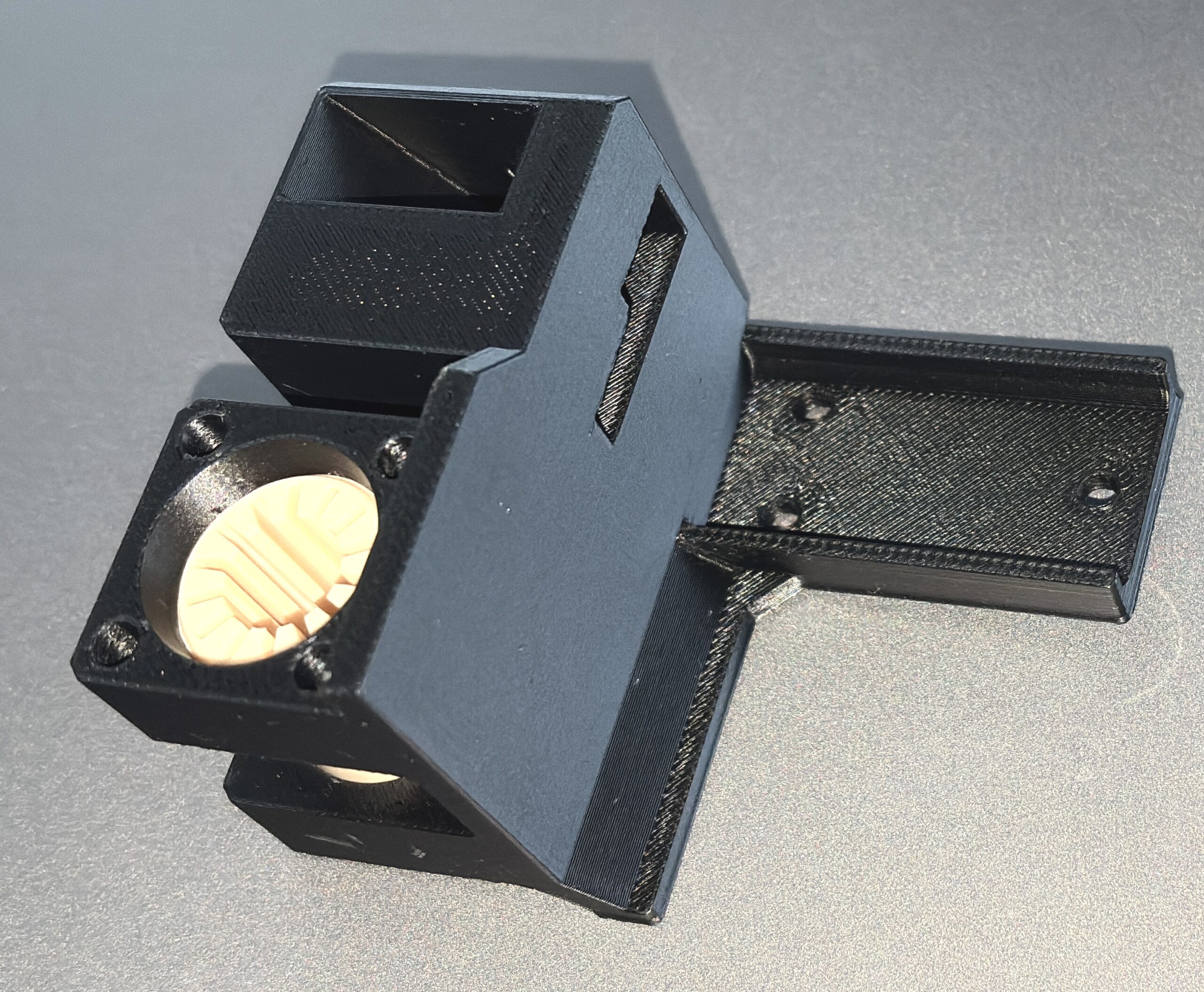
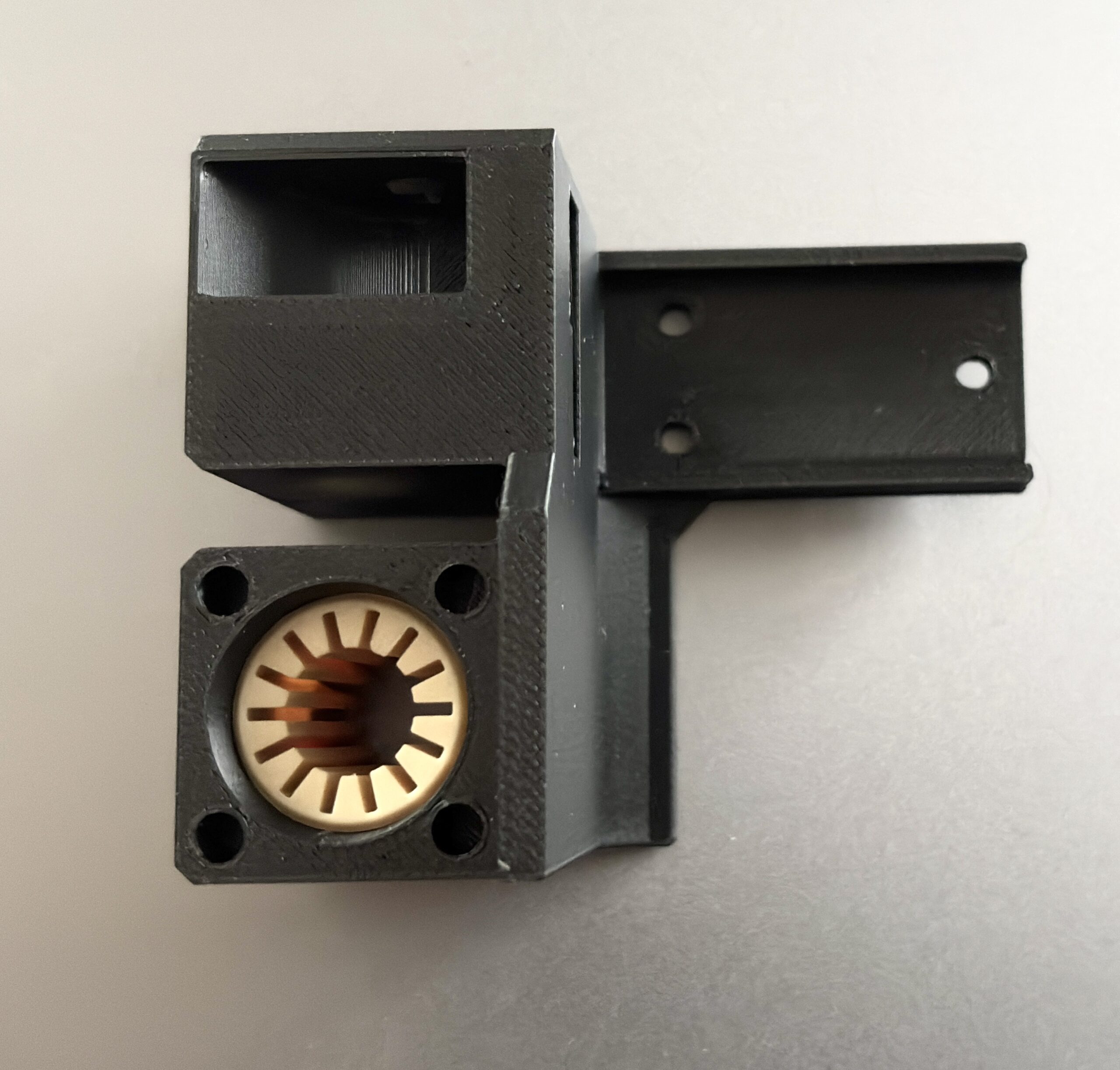
The bearing in the picture is purely for testing dimensions. The PETG is too soft and unstable. Two bearing covers are still missing to prevent the plain bearing from sliding back and forth.
I am looking forward to the before and after test.
Mods for Core One: Core One HT 450 degrees, Comfortable display , Very fast print start and Reducing noises
Mods for Prusa XL: Very fast print start
RE: Gantry resonant mode and VFA artifacts
The discrete jumps mark spots where I changed the print speed. I started at one speed and increased the speed in 10mm/s increments every 15 layers or so. The idea to find out which speed was worse, then infer the resonant frequency from that (basically, divide by 2 to get Hz, since the spacing was at 2mm).
When I look at those pictures on page 1, the VFAs seem to change amplitude suddenly at discrete heights. Most VFAs on my printer run the entire height of the part, save for about 3 mm near the build plate that's glossier. Does that vertical spacing correspond to anything?
RE: Gantry resonant mode and VFA artifacts
If you mean the red and blue traces, those correspond to each of the 2 accelerometers. I used two, one attached on the left and right side of the gantry. I forget which one was left and which was right but that ended up not mattering.
If I assume that each Hertz in the diagram represents the resolution of the scale (x-axis/time of the top diagram measured for the x-axis) at a sampling rate of 400 Hertz, then the peaks/sine curves, for example, between 10 and 20 (almost two of them), can correspond very well to the teeth at 90 mm/s. What puzzles me is that there are two sine curves instead of one. Either it's the tooth during engagement and disengagement, which would explain the two, or the second sine curve is the resonance.
RE: Gantry resonant mode and VFA artifacts
I notice that the frame of my Core One flexes quite a bit while printing.
yes... for the accelerometer data it may be significant when the print bed is moved by the "recoil" from the steppers, shaking the whole printer.
For Gyroid infill, the displacement seems much larger (even mm?) than VFA depth (tens of µm?) but those are much more energetic moves than perimeters where VFAs would matter. Nonetheless, an accelerometer on the head (or the gantry) may not tell the whole story.
RE: Gantry resonant mode and VFA artifacts
Minor update: I've been focusing on the print head itself. Originally I'd avoided it because of course the print head is moving, that's the whole problem. But I realized there's quite a bit of mass on there, most of it top-heavy instead of centered closer to the linear rail. So any very slight axial wiggle about the gantry's centerline, combined with the print head's offset mass leads to a strong resonance. Indeed the top of the print head is shaking like crazy. I'm now focusing on mitigation as redesigning the gantry with two smooth rails or to have a more centrally located mass is likely out of the question (at least with my skills). I did disassemble and reassemble the whole print head & linear bearing attachments point just to make sure there wasn't anything loose or a pinched belt or something. No effect.
I'm going to take a step back from this for a while and focus now on mitigation, i.e. avoiding driving the resonance in the first place. The input shaper routine finds the strong resonances right about where I'm finding them too (~45 Hz). Interestingly, the pre-programmed input shaper frequencies are at 50 & 60 Hz so quite a bit different than that. Of course, enabling input shaper at the correct frequencies doesn't seem to help much either but there are still a lot of parameters to play with, so that'll give me plenty to mess with. Also planning on trying some of the recommendations from the other thread: 1.5mm belt and new pulleys, not that I expect it to really change the basic behavior that dramatically, but maybe it'll make it more manageable.
RE: Gantry resonant mode and VFA artifacts
That's an interesting observation. When I do photography on a tripod, I've found supporting the mass at the balance point is important. I've even made adapter plates that shift the mounting point to the balance point. Better to be at the COG, but that's inside the lens! A cantilevered mass is always bad for resonances because it pretensions any springy bits. Naturally a big problem in a moving system. One technique people use with structures is to mount an accelerometer at critical locations, then start (gently) hitting various parts with a semi-soft mallet. That can pinpoint what joints and interfaces are insufficiently rigid. Alas, I have a lot of measuring equipment, but not the time to investigate as many things as I'd like.
RE: Gantry resonant mode and VFA artifacts
Just summarizing my tentative conclusions (and only my own, this qualifies as at best a semi-informed opinion, not facts):
There is a resonance driven by belt-induced noise that causes lateral (front to back) motion of the gantry along the smooth rails. This interacts with the relatively heavy mass of the print head and extruder, which is only supported by a single linear rail. So the print head "flaps" back and forth. This is a relatively low-frequency mode in the range of 45-60 Hz.
There is rather wide variability from unit to unit, probably based on some build variation but at least some of the evidence seems to point to the L brackets being one source of variability. I was able to push the resonance up in frequency somewhat by tightly shimming the L brackets.
The Core one ships with a default set of input shaper settings of 50 & 60 Hz. My resonance is lower, around 45 Hz. For people with a primary resonance in the 50-60 Hz range, the default coefficients are almost certainly masking the issue. I have been having some encouraging luck messing with different input shaper settings.
I swapped out my belts for 1.5mm belts this morning and it does help my case, but mostly only the amplitude of the oscillation due to the smaller forcing of the smaller teeth. The resonance is at the same frequency (in Hz) but shows up at a different belt speed due to the finer spacing. I wouldn't recommend it as a permanent fix, but for me it works because it pushes the resonance into a belt speed range I don't use as often.
Printing faster does improve things as well, since you'll stay well above the resonance.
I suspect Prusa already knows most of this and isn't eager to volunteer that a single linear rail isn't providing enough support to the print head and extruder. The next best thing you could do is to push the resonance upwards which is what the belt tension recommendations are all about. I think supporting the print head at the top would help with the flapping mode, but that's frankly just guesswork right now.. need experiments or FEM simulations.
RE:
Has anybody looked into the print fan? The one in my Core One resonates quite cleanly on its bracket at exactly 50 Hz (eyeballed, or should I say "ear-balled" using an online frequency generator).
This can be easily improved e.g. with a piece of TPU (picture) as I will try.

RE: Gantry resonant mode and VFA artifacts
... additionally, I noticed there is a fair level of "buzz" even while the head is stationary just changing filament over the wipe tower with the MMU.
Could it be that vibrations are induced by print- and/or cold end fan imbalance? 3000 RPM (which doesn't seem off for the fan size) is 50 / s...
RE: Gantry resonant mode and VFA artifacts
Hello everyone.
I have now read various topics in the forum and on the Internet and have installed a plain bearing in the Y-axis.
I personally find the result impressive.
https://www.printables.com/model/1602328-prusa-core-one-resonance-noise-eliminated-with-sli
Now I'm going to take a VFA test.
Mods for Core One: Core One HT 450 degrees, Comfortable display , Very fast print start and Reducing noises
Mods for Prusa XL: Very fast print start
RE: Gantry resonant mode and VFA artifacts
I have now read various topics in the forum and on the Internet and have installed a plain bearing in the Y-axis.
I personally find the result impressive.
https://www.printables.com/model/1602328-prusa-core-one-resonance-noise-eliminated-with-sli
Now I'm going to take a VFA test.
Nice! I am not bothered by noise (yet), but can't wait for your VFA results!
The Printables headline talks about "Replacing the linear bearings on the MK4S", which I found a bit confusing. Is that meant to refer back to an already proven solution in the MK4S? Still it might be better to mention the Core One explicitly right up there.
RE: Gantry resonant mode and VFA artifacts
Hello everyone.
I have now read various topics in the forum and on the Internet and have installed a plain bearing in the Y-axis.
I personally find the result impressive.
https://www.printables.com/model/1602328-prusa-core-one-resonance-noise-eliminated-with-sli
Now I'm going to take a VFA test.
Interesting! I might (attempt to) print these out of POM. If that doesn't work, I also have a roll of Igus i150 I haven't found a use for yet.