XL Filament Sensor Mod for TPU
Hi,
Just wondering if anyone has tried making the pressure of the filament sensor lower for use with soft TPU materials like ninja flex and if so how it was adjusted (spring replacement or something?).
The problem I am having is that it's a massive pain to try and push a soft TPU into the filament sensor and then try to push it all the way to the extruder and then get it to go past the filament sensor in the extruder. So far I have had to use pliers to help push the material 2mm at a time then once it's at the extruder I take off the ptfe tube and try to pull some extra out (which takes a lot of force) to manually guide it around the extruder gear to prevent it from bunching up. I imagine making the resistance from the filament sensor lower should also help with printing of the soft material since it won't be stretched as much and the diameter will be closer to the starting 1.75mm.
Any thoughts would be appreciated.
Thanks
RE: XL Filament Sensor Mod for TPU
thought the same during during first startup and modified the parts, have at it
https://www.printables.com/model/585694-xl-filament-sensor-reduced-force
RE: XL Filament Sensor Mod for TPU
Thank you for the model link. I ended up going a different path by removing the springs all together. Instead I got some 3mm diameter and 3mm long magnets (I found 500 pieces for $8 on amazon) and used them to repel and attract the original magnet with the ball bearing. The magnets repelling each other is similar to what was done with the Mk 3S+ extruder filament sensor - which I didn't have any problems using TPU with. I will attach pictures of what I did on the XL.
For the extruder filament sensor, I took apart the extruder assembly by removing the gear box cover, gears with brass section, and the last plastic insert that helps guide the filament. I then pulled out the filament sensor housing with small needle nose pliers (should come out easily). The ball bearing/magnet and spring should fall out when the housing is tipped over.
Layout of the magnets to be put into the sensor housing. I had to use a hex key to guide the first magnet to go in the correct way and the small rod to temporarily pin the magnet in place to remove the hex key and place the original magnet back into the housing.
Make sure magnets are repelling each other. the bottom magnet should be captured in the housing so no glue was needed to keep it in place.
Filament sensor housing installed back into the extruder assembly.
If you look close you may be able to see the filament side magnet move from the no filament inserted picture above.
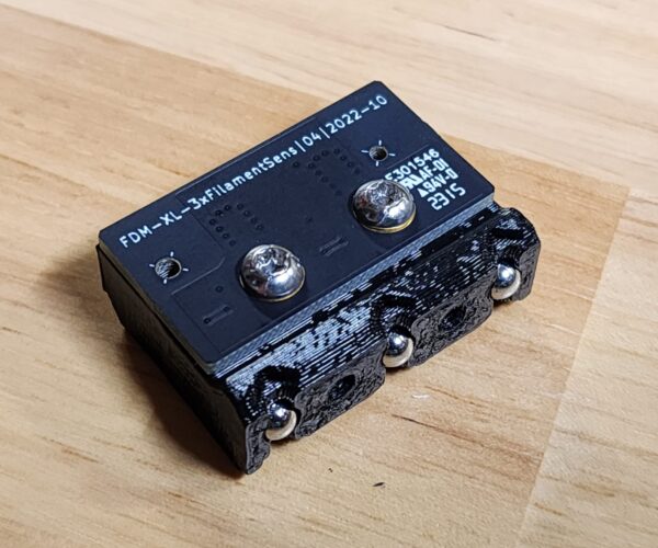
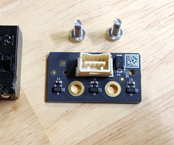
On the side mounted filament sensor the new magnet in place of the spring did not allow for proper function of the hall effect sensor so I had to take a different approach. For this sensor I mounted the new magnets on the outside of the housing so that they would attract the original magnets. I used the same 3mm diameter and 3mm long magnets from the extruder sensor change. First step here was to remove the sensor housing and take out the sensor board assembly, remove the board, and take out the springs.
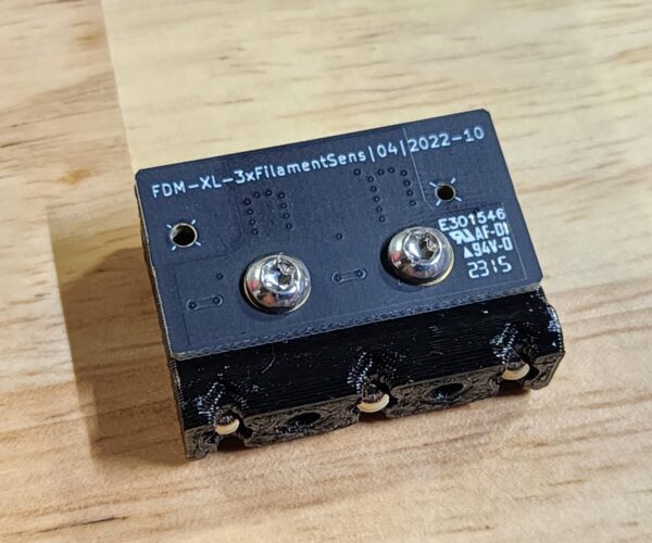
Springs are removed and the magnets with ball bearings seem to be captured in the print. The board can be screwed back onto the plastic part.
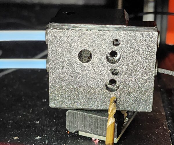
Taking a look at the outside housing of the side mounted filament sensor I drilled a small ~1.5mm hole in the middle of each of the filament channels where the ball bearing would be from the board holder part.
All three small holes were then drilled from the outside of the part. I used a 3mm drill bit to make holes about 3mm deep (this happened to be where the infill and the next wall layer was). Make sure there aren't any extra pieces of plastic in the filament paths or new holes for the magnets.
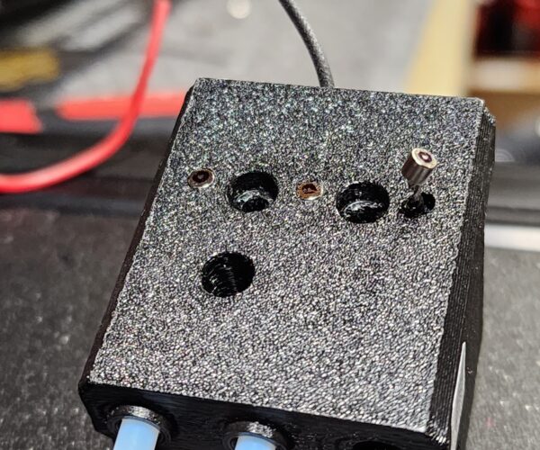
Now I marked the magnets to make sure I had the correct orientation so that they attract each other. Then I pressed them into place from the outside. The small drill bit can be used to push out the magnet if you find its not the correct orientation. I may put a small piece of tape or glue over the magnets so they don't accidentally get removed.
Lastly, I did a final check to make sure that the magnets attracted each other with the two parts assembled together. You can see the two ball bearings in the left side and right side holes.
Finally, reassemble everything and perform a calibration check of the filament sensors to ensure everything was done correctly. I was able to very easily push Ninja flex TPU 85A from the roll past the side filament sensor, all the way through the PTFE tube and into the extruder filament sensor to trigger the automatic loading sequence (almost like it was a regular rigid filament).
Now I just need to test out a print and maybe make some settings so the ninja flex doesn't jam between the nextruder gear and the nozzle tube.
RE:
I see you have taken the side filament sensor apart 😀
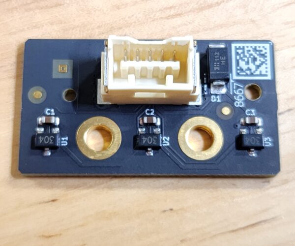
Could you please share a closeup picture of what the other side of this board looks like? I am wanting to relocate these sensors to the rear of the printer, but don't have my XL yet
www.antalife.com
RE: XL Filament Sensor Mod for TPU
Thanks heaps 😍
www.antalife.com
RE: XL Filament Sensor Mod for TPU
In a semi-unrelated question, does anyone know if the orientation of the sensor matters? I'm curious if it can be mounted vertically instead of horizontally.
Aaron
RE: XL Filament Sensor Mod for TPU
I would also like to modify on the filament sensor setup but do not want to start designing any special pcb. Would it be possible to wiring 3 filament sensor boards in parallel and use just a single filament path. would these boards work that way in an OR logic function? It seems that way but maybe someone has more insight.
RE:
One thing I've learned thus far is that the housing has been designed such that the standard PC4, external hex connectors aren't going to fit. Thankfully, there are some options out there I'm exploring.
Because likewise, I don't want to mess with the PCB.
Aaron
RE: XL Filament Sensor Mod for TPU
The hall 304s if I connect let’s say 3 of those FDM-XL-3xFilamentSens in parallel should provide logic 1 as long as one of the paths on one of the boards is loaded with filament
RE: XL Filament Sensor Mod for TPU
Hi @Antalife
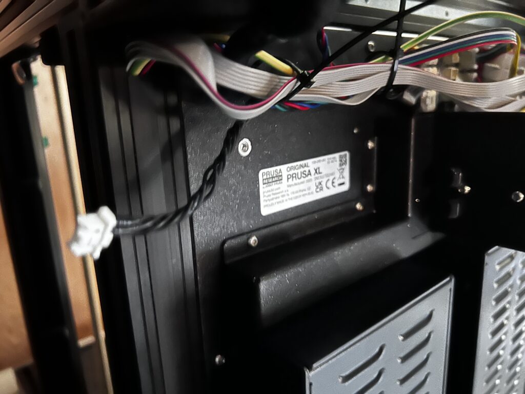
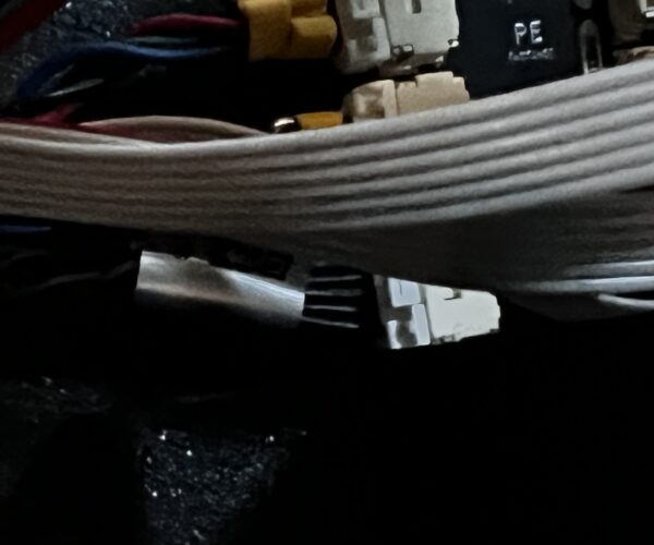
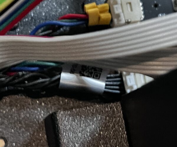
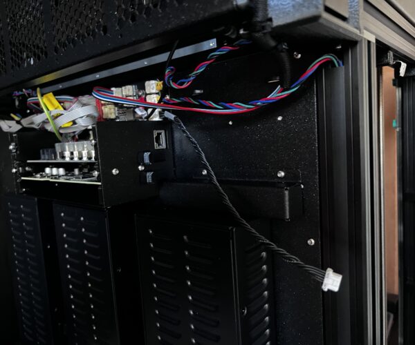
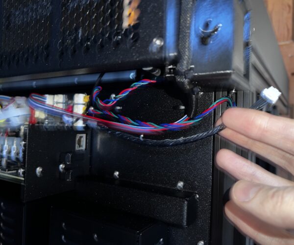
If you’re looking at moving the filament sensors, these photos might also help. If you can sort additional extension wires/connectors out it should be a pretty simple job…
Here are the molex connectors. Go to Digikey they have them. You will also need the molex .062 male and female pins. The WM number is the stock #. They have the pins on Amazon.
RE: XL Filament Sensor Mod for TPU
I've ordered a second left-hand sensor (answering my question about whether they made two different parts). I will use the PCB on that one for my modified filament sensor housing, as I'm not quite brave enough to assault the working one I have now.
Aaron
RE:
ordered those connectors figured out i already had a digikey account 🙂 earlier project thanks for part numbers i want to mount my spool
in a wall mount system being able to extend these will work out great
RE: XL Filament Sensor Mod for TPU
I've ordered a second left-hand sensor (answering my question about whether they made two different parts). I will use the PCB on that one for my modified filament sensor housing, as I'm not quite brave enough to assault the working one I have now.
I am with you on this. I ordered one as well. Also ordered the new connector ends to make a longer cable. Eventually I am going to try and feed the filament through the top of the enclosure.
RE: XL Filament Sensor Mod for TPU
That’s what I am about to do too. Although I will wait another decade for the enclosure 😆
RE: XL Filament Sensor Mod for TPU
Here are the correct pins. They are 1.5mm square inserts. Digikey has them .38 cents for 10.
Molex 502579-0000
RE: XL Filament Sensor Mod for TPU
Here are the correct pins. They are 1.5mm square inserts. Digikey has them .38 cents for 10.
Molex 502579-0000
Don't forget you can also buy pre-assembled cables:
https://www.molex.com/en-us/part-list/15135?taxonomyPathValueLast=Power%20and%20Signal%20Cable%20Assemblies&physical_circuitsMaximum=5&materialMaster_promotable=true
www.antalife.com
RE: XL Filament Sensor Mod for TPU
Here are the correct pins. They are 1.5mm square inserts. Digikey has them .38 cents for 10.
Molex 502579-0000
Don't forget you can also buy pre-assembled cables:
https://www.molex.com/en-us/part-list/15135?taxonomyPathValueLast=Power%20and%20Signal%20Cable%20Assemblies&physical_circuitsMaximum=5&materialMaster_promotable=true
Good find.
RE: XL Filament Sensor Mod for TPU
My sensor came in today, so I tore it down as far as I was willing to take it.
This is the insert that holds the PCB, springs, and bearings. It fit snugly into the main body of the sensor. So much so that I had to apply a bit of pressure to coax it out.
Now I've got the PCB off, and I'm stopping because there's no real point in removing the bearings and springs just yet. You can see, based on the CAD model, that there's a pocket for the spring, and a bearing is press-fit into the space above it. The bearing is retained by the interference fit, and the spring keeps tension on the bearing.
Now for the cool part and what I didn't realize or expect. The little fittings here are push-to-connect connectors and are the smallest I've seen. I purchased two styles that I thought were rather compact, and they've got nothing on this. The red arrow points to the little metal 'blades' that help retain the pushed in tubing. This ultimately simplifies everything for me, and I've wasted money trying to re-engineer something Prusa has already solved.
So now it remains for me to figure out how to move this sensor to a location that works best for my particular installation of the XL.
Aaron


