RE: I found serious design error in MMU2 electronics hardware
Please remember that Prusa is still not a massive multi-national company with 100s of software and hardware developers. They now have to support MK2.5s, MK3s, MINIs, SL1s/CW1s, MMU2s, PrusaSlicer, and the R&D of future products. The MK3S and MMU2S was released in Feb 2019 and the MK3S+ in November 2020. Bare in mind that during that time and up to now the whole Pandemic has been going on! They might have planned for a MMU2s+ for all we know but it had to be delayed. (No insider knowledge, sorry). Or maybe they've decided to skip the MMU2S+ and go for a MMU3 with major redesigns?
There have been some hardware (3D printed) updates since 2018 so they have still been working on things.
Considering how many companies have had to close for the last year and a half we should probably be thankful Prusa has managed to stay running during it all.
Let's look on the positive here, someone has found a fault and a fix and had the decency to share it with everyone, including the technical details with Prusa. So give the USB technique a try and see if it solves some of your problems with the MMU2(s).
RE: I found serious design error in MMU2 electronics hardware
@kennd
Hi, if you look very closely at my post you‘ll see that I responded to 3delight‘s post ( „Posted by: @3delight“) and not heine-mau‘s (kudos to him for being able and qualified to find such a design flaw and kind enough to do so and post it). I too have an MMU2, and it‘s working quite well and I would be delighted if development and support of that thing would continue and prosper - I just have serious doubts that it is.
So I‘d like to know and hereby clarify my question: does anyone at prusa care?? Do they still work on developing and improving the MMU2?
If at first you don't succeed, skydiving is not for you.
Find out why this is pinned in the general section!
RE: I found serious design error in MMU2 electronics hardware
Hello all;
The process for submitting a issue to github was provided and followed. Those tickets go directly to the developers and are assigned.
If development on the MMU project was terminated, it would be announced (the same where a product reaches its service life and is phased out in production), and the moderator would have instead said that the project was discontinued, but that is not the case.
The Pandemic really has taken a toll in many different areas. This is not an excuse but unfortunately a fact. If you look at the companies track record we release new products on a yearly basis, and with those innovations, if there was a feature that could be carried over to a previous model it was done so. That is where the .5 or S iterations come from.
The MMU project is still active and is always being worked on. For this particular case, as said before, it has been submitted and will be reviewed. If there is a benefit and can be worked into a future version of the MMU and also be carried over to older units, it will be done so as well. As far as a time line on this. Unfortunately, that I can not say. While there are signs of some areas of the world improving from the pandemic, other places are not. Even more recent events, (for example) the blockage at the Suez canal, while not directly affect one company, it could affect a different company that supplies goods (I am saying that ONLY as an example of things that can affect development for any company).
We love innovating and continue to develop new products and also improve on existing ones. As much as people want us to release new types of machines, we want to get them out there and we are working on that while navigating a lot of challenges that pop up at random times that are well beyond our control. In time things will return to normal and we will catch up and be back on schedule of things. In the mean time we do need to be patient.
Thank you.
Shane (AKA FromPrusa)
RE: I found serious design error in MMU2 electronics hardware
Thank you for sharing this information! I’ve been have the same problems with my MMU2S. For now it’s back to working ok by changing the mmu mode to normal, but I’m sure that’s just a temporary fix.
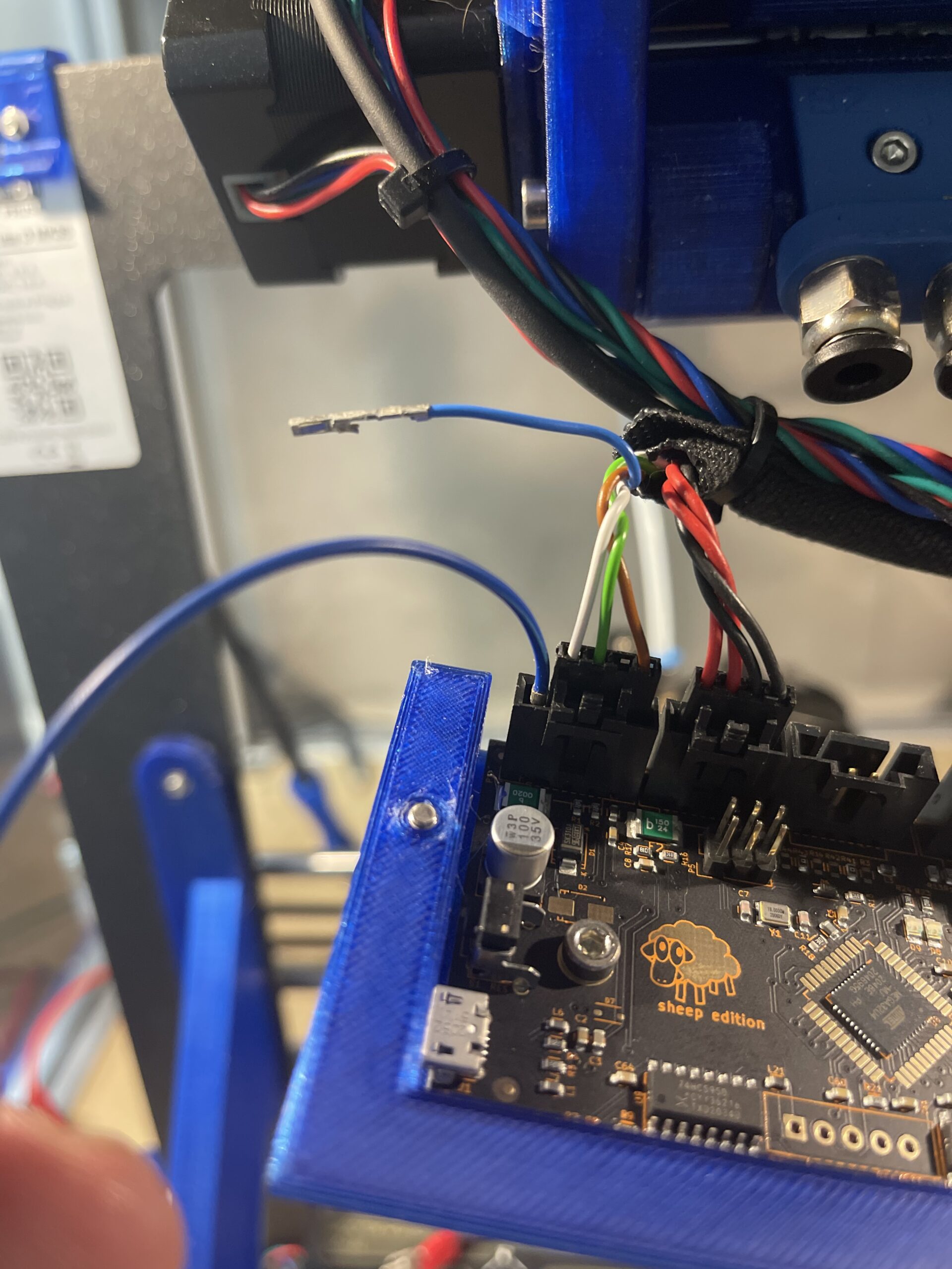
What about adding a separate 5V power supply, that can be adjusted to give 5V after the D1 diode? I’ve been looking at some Meanwell modular supplies, and I was thinking that might be a way to send 5V to the P1 connector on the MMU2S board, instead of pulling it from the Einsy board.
I am a Bachelor in Electronic Engineering, with 15+ years experience in MCU HW/SW....
I have had a lot of problems with my MMU2. Before i upgraded my I3MK3 was perfect 🙂 but the MMU2 changed that...
The problem I found is that the 5V supply on the MMU PCB is only 4.2Volts - witch is too little for the MCU/stepper drivers.
The problem can be reduced by attaching some USB host to the MMU - only as extra power supply (no need for software on the host). That raises the +5V by a 50-100mV in my case.
As a proof f concept i made a little risky mod on my MMU2 PCB to test my theory: Shorted D1 and added 1000uF from this short to ground. Since i did that i have had a very well working MMU2. With a 4.8Volt on the +5V supply net.
Somebody at Prusa should take a look at this issue.
...Your welcome 🙂
RE: I found serious design error in MMU2 electronics hardware
So FWIW I decided to add a DC to DC converter to my printer, 24V to 5V, to replace the 5V coming from the Einsy board I adjusted the converter so that I’m getting a true 5V after the D1 diode.
I have never run a true MM print, as I only print a disc of one color with text of a contrasting color on top. That alone has given me no end of headaches. So after adding the supply I decided to try and print a 2 color Gecko, and amazingly (to me) it worked flawlessly. Only time will tell if this is a fix of sorts, but here’s hoping!

RE: I found serious design error in MMU2 electronics hardware
The problem I found is that the 5V supply on the MMU PCB is only 4.2Volts - witch is too little for the MCU/stepper drivers.
Interesting find! What are the symptoms of too little voltage? I haven't noticed anything (and what are good points to measure the 4.2V?)...
RE: I found serious design error in MMU2 electronics hardware
Mirar,
Many of us are experiencing frequent MMU resets and stalls mid print and during filament changes. Usually the stall results in all 10 filament lane LED blinking requiring a reset of the MMU to continue.
Adding a USB power supply to the port on the MMU does improve MMU function for most, but I still get the occasional stall. I did find it necessary to use a USB power supply with a 5.2VDC rating, most are not.
There is a post somewhere (I no longer have it handy) which shows a measurement point. On my board it was 4.1 volts without the USB power supply and 4.9 volts with the USB power supply.
I tried all the advice to correct my problem before adding the USB power supply. I even purchased and installed a new control board, but the USB power supply seemed to do the trick, at least most of the time.
I am still looking for a better solution.
If you don't experience these problems it's probably not worth pursuing.
RE: I found serious design error in MMU2 electronics hardware
I used to have it connected to the raspi (I was hoping to be able to flash it from octoprint and just left it there), so maybe that's why I haven't seen the problem... I haven't had that for a few months, but I also haven't used the MMU more than in the beginning of prints. I'll add it back. Doubt it will solve my current issue though (see other thread).
RE: I found serious design error in MMU2 electronics hardware
The problem is that the MCU (=CPU) is not able to run at the set speed with less that 5.0 Volts supply.
The speed is fixed, and thus the consequences are everything can fail - often, seldom, rarely or never.
Just to mention a few:
- flash read error => wrong instruction is executed / wrong parameters used
- RAM read / write error - some random variable gets a random value
- UART / SPI interface could send out wrong information to stepper driver (assuming SPI is used)
- Anything, anywhere anytime 😀
Short story long: anything can happen, often or never 🙂
I agree with the point from Lynn: if your MMU2 is working fine, then simply consider yourself lucky - you got a 'sunshine' MCU 🙂
I must say i was impressed by the Prusa Mk3i3, but everything else from that company has been very poor.
....and today my core-xy printer is 10x better that that old i3 (the MMU2 is waiting for the garbage car to collect it)
Prusa was.
RE: I found serious design error in MMU2 electronics hardware
Oh man this thread is awesome. So I too had all lights blinking mid print. I could sometimes recover with MMU reset, but several times it would just lose its mind, and the print would just fail without getting the printer and MMU to work together again. I heard about plugging in an external 5v into the micro USB port, and that seemed to help for a while but the issue came back. I tried using TheZeroBeast custom firmware and it seemed to work better. No more all lights blink and power failures. But it would fail to unload, and the MMU idler wheel would sometimes be on the wrong position so it would eject the wrong position. Still it didn't need a reset to recover. After a manual unload and rehome it would continue. The problem was this failure type happened frequently. Every 10 changes or so I'd have to fix it. So I went back to the official firmware, but got power issues again. This makes me think is TheZeroBeast masks the power failure issue a bit, where the original firmware faults and dies. TheZeroBeast just keeps going without a fault and hopes it can continue. In my case it couldn't.
I probed my 5v and it was 5.01v coming into the MMU. One side of the D1 diode was 4.8v, the other side was 4.4v. I cut into the harness and put in my own 5.2v DC DC converter from the 24v, and so far everything is working great again. My MMU2 I bought was also one of the earlier ones, and I'm wondering if newer revisions fixed this issue. Still I'm happy I didn't have to put more money into fixing it.
RE: I found serious design error in MMU2 electronics hardware
Does anyone have more detailed information about the correct connector & pins, how to add the DC to DC converter into my own system correctly ?
The topic is already almost a year old and I doubt that prusa has fixed this issue on their currently on sale MMU2 electronics board, so this modification might be really helpful to a lot of MMU2 users out there, but I feel that a little bit more detailed information might make it easier for people to do this modification themselves.
RE: I found serious design error in MMU2 electronics hardware
I am using a phone charger as power supply for the MMU2 right now. Significant less blinking lights but still sometimes. I am planning to install a converter with 5.2V soon. I‘ll post pics and specs when I am done. Might take a few weeks though..
If at first you don't succeed, skydiving is not for you.
Find out why this is pinned in the general section!
RE:
Does anyone have more detailed information about the correct connector & pins, how to add the DC to DC converter into my own system correctly ?
The topic is already almost a year old and I doubt that prusa has fixed this issue on their currently on sale MMU2 electronics board, so this modification might be really helpful to a lot of MMU2 users out there, but I feel that a little bit more detailed information might make it easier for people to do this modification themselves.
The pictures in this thread helped me figure out what was needed. I used one of the buck converters I had on hand from Amazon. It has a screw that you can adjust to change the output. I wired the 24V from the output of the PSU directly, into this converter. Then the output of the converter I spliced into the harness going to the MMU, from the main board. I cut the blue wire (as shown earlier), then wired the output of my DC DC converter positive to the blue wire going to the MMU, and taped up the output of the main board since it isn't needed. I then took the output of the buck converters negative and wired it to the negative going to the MMU which was one of the black wires. The two seem tied together, likely for more current so I don't think it matters which. Then I put a meter on the side of D1 and adjusted the DC DC until it was 4.6V, which happened to be around 5.2V out of the converter.
There are some concerns with this mod. Like when you are flashing I'm worried that the higher 5.2V is going to go to the USB port of the computer. I did successfully flash it but I do wonder if it could back feed. I also don't know if over time the converter will drift. These are cheap, and may not be 5.2V years later so I plan on checking it periodically. The current draw on this is probably really small, but I forgot to check it. 24V is being piped in separately, and this 5V is likely only needed for low power things like the communication and microcontroller. I haven't been able to run much since making this change, but so far I haven't seen any all lights blinking on original firmware, or odd idler selector on TheZeroBeast.
RE: I found serious design error in MMU2 electronics hardware
After several yeah... Yes first buyer of mmu2 and upgrade in mmu2s. I have found same problem in my mmu2... Lost of tension in 5v power supply. My job is electronician and its my work 😉 this design have a big error. To mutch lost of tension in the input of the 5v. One thermal fuse (lost 0.2v) and a reverse protection diode (0.5v) its to mutch tension lost 0.5-0.7v lost before the MCU.
I have put a small switching power supply in 24v to 5v sink power in the 24v input of the mmu2.
After that's no more random leds blynking, random Motor unlock, homing fail... It's perfect 👌
RE: I found serious design error in MMU2 electronics hardware
I have to say that I'm little bit dumbfounded that this issue has been reported almost a year ago and there hasn't been a single acknowledment from prusa.
I don't expect miracles, but this has been plenty of time to figure out some sort of solution for this problem and still there is nothing "official" as of yet.
Even the github issue doesn't have anything from prusa. Please, if there is somebody working on this, just mention it somewhere.
I agree 100%. This is a serious HW issue that directly impacts the functionality and reliability of the MMU2. I've been chasing my tail for many days trying to get my MMU2 to even load filament reliably. I attached USB power and most of the problems I was having have gone away, though I'm pretty sure I am still seeing some consequence of the problem.
I am planning to add a DC-DC converter as others have done to take 24v from the PSU and provide the expected voltage to the MMU2. When tuning the output voltage, is there any reason not to ensure a full 5v on the +5v net (e.g. on the inboard side of D1)? I see others mentioning bringing it to 4.6v, but since I'm dialing it in, why not provide the expected 5v. I'd hope that there isn't an issue of back feeding the higher voltage into USB as there is a similar diode between VBUS and +5v (D7).
RE: I found serious design error in MMU2 electronics hardware
My big question is:
Is that Diode D1 for protection against reverse-polarity really needed?
Just bridging that diode is much easier in many aspects than to patch the input-voltage to something higher (especially the risk of backfeed into USB...).
Since we appear to have that many specialists here - does no one have an oscilloscope that he can hook up to the power-supply-side of the MMU? That way we can see what happens there when you switch the printer on, and whether that protection is needed or not.
My personal opinion and hope is: It is only there to comply with good practices of designing a circuit, but not needed in this specific application. And so it can go...
RE: I found serious design error in MMU2 electronics hardware
Since time to edit seems to be expired while editing...
Here's an addendum to my previous post:
As reported in this post here:
I have changed the mmu-board. As one of the pre-orders, I had revision "2018-04-04 rev 0.3", the new board has "2019-09 rev 0.4.4". I also noted that the resettable fuses were both doubled in value. So far not one error, testing is still ongoing though... My initial guess from way back then was a hair-crack in the board, or that the ageing of a component had the effect of voltage drifting outside of permitted value. The topic of too low voltage due D1 is absolutely sound, but the problem seems a bit random to make it "THE" problem. Maybe it's more a contributing factor?
RE: I found serious design error in MMU2 electronics hardware
You can do this modification easily with a iron solder. Juste, if you try this, remove the power cable of the MMU before update or use USB input. After the remove of the diode, the USB can power back the Main board of the Prusa MK3 and i's not a good idea XD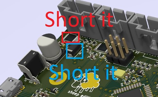
RE: I found serious design error in MMU2 electronics hardware
Thanks Skulbl4k4 for your clarification!
...but...
Whenever you do an update, the whole printer is running anyways...
...and since there is some voltage-loss over the cables for power-supply between printer and MMU...
...I cannot see why that would be a problem...?
Even if I'd supply the main 5V-circuit from the MMU by USB I would not care that much? Since all should just be controlling circuits which should have a low consumption...? The 500mA from USB should be able to handle this...?
Has no one probed yet what happens at the switch-on? Is reverse-polarity really an issue...?