filament sensor modification
I am trying this mod because it requires no firmware changes Has anyone here tried this version?
https://www.thingiverse.com/thing:3129921
the author sends you to this page in the german section here for questions
https://shop.prusa3d.com/forum/benutzermodifikationen-octoprint-gehaeuse-duesen-%E2-f2
'/neues-filament-sensor-gehaeuse-t24920.html
so I am just using the read me file he wrote for thingverse which I append at the end of this
my prints turned out OK in PETG and I can clean out the path for the PTFE with a 4mm drill
I think he intends one of his top designs for a Bowden coupler and another for a deject ptfe tube connection but I am not clear which is best for the person without the MMU2
and I have the needed bearing
here are my prints which go together well
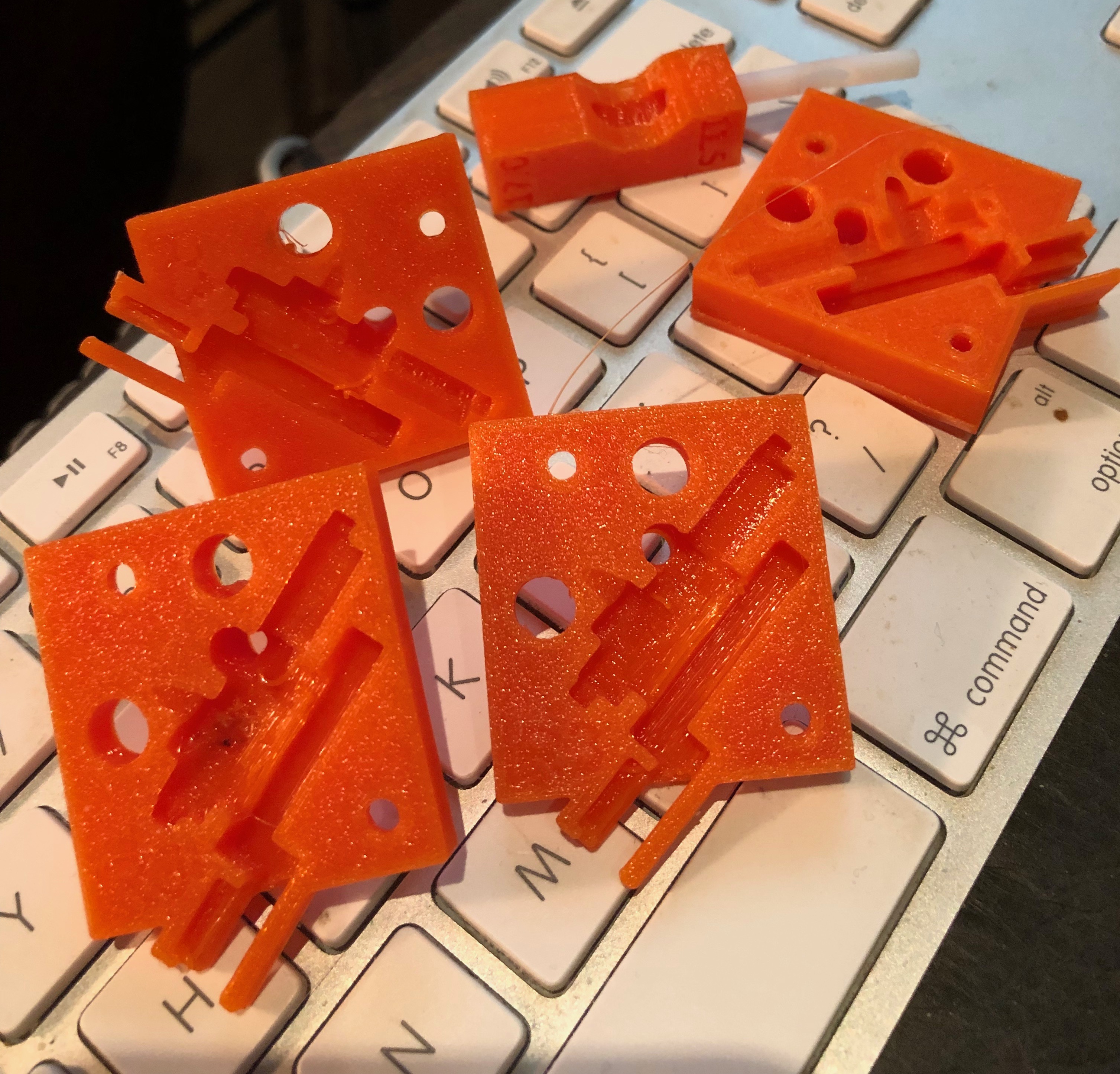
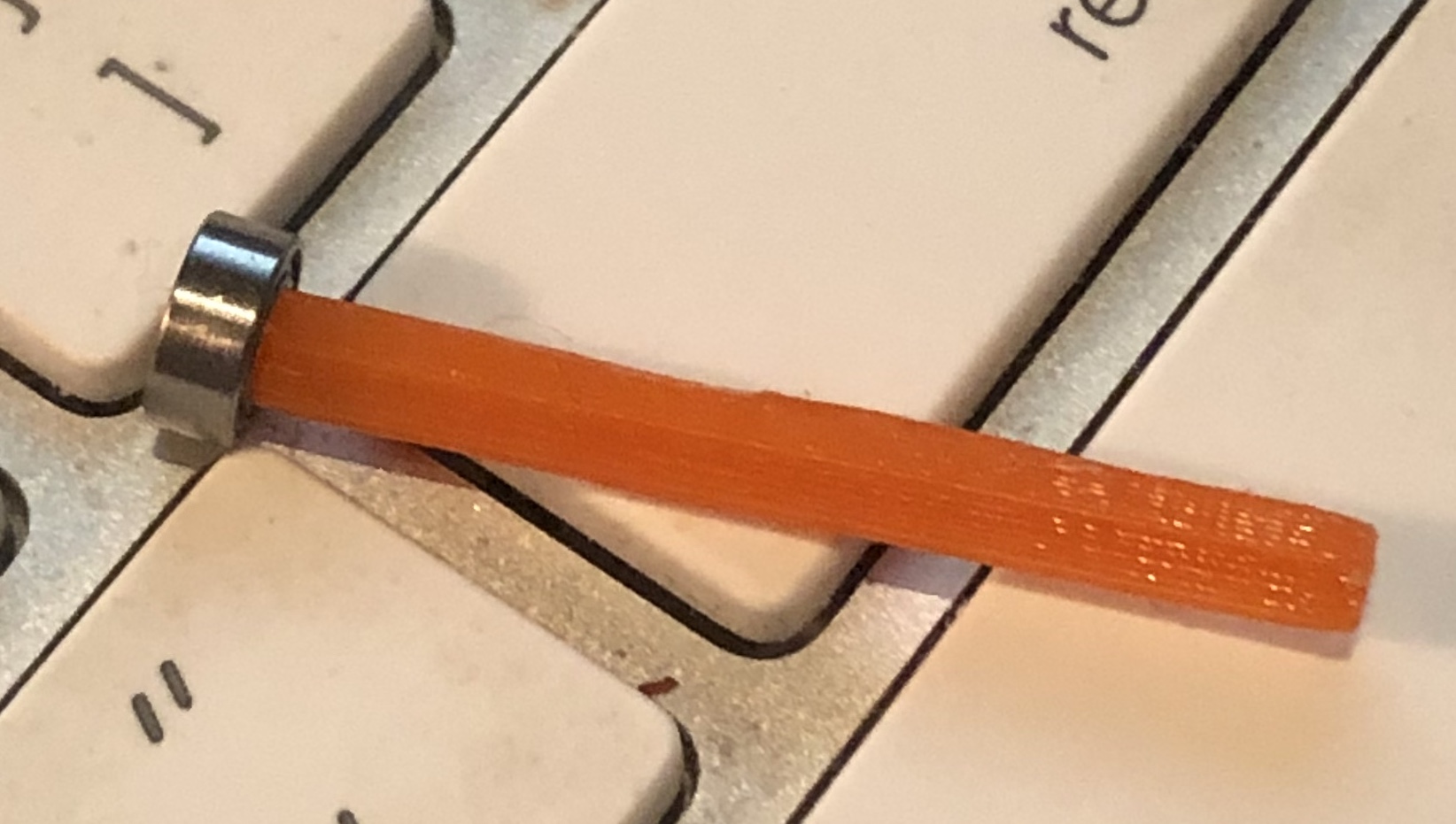
but I had to use a brim to print the spring/axel and it will take quite a bit of sanding to move the bearing down to where it needs to sit I assume that ID of the bearing is to be jammed on the spring so I thought of printing it at a reduction to say 80% to cut down on the sanding but I don't want to interfere with its spring function by making it too thin so that the ID also spins on the spring.
thoughts anyone?
http://www.thingiverse.com/thing:3129921
Prusa I3 MK3 - New filament sensor adapter in a separate housing by SIE-Maker is licensed under the Creative Commons - Attribution license.
http://creativecommons.org/licenses/by/3.0/
# Summary
Prusa I3 MK3 - New filament sensor adapter in a separate housing.
Get rid of fake alarms from the filament sensor!
10/02/18 Great News! V2 Upgrade with adjustable spring force!
With an additional M3x16mm screw on the left bottom side, it is now possible to fine tune the spring force for the ball bearing! This extension is especially useful for MMU owners.
Applies only to Part Top (A) and Part Bottom (B).
Recurring false alarms from the filament sensor of my Prusa I3 MK3 have urged me to look for a solution, Firmware 3.3.1, 3.4.0, now 3.4.1-RC1.
The cause of the false alarms are insufficient light reflections from the filament used.
Particularly shiny or transparent filaments provoke a too weak recognition with the optical motion sensor.
In order to avoid this circumstance, the filament movement is transmitted to the sensor via a small ball bearing in my solution.
The sensor thus sees only the movement of the ball bearing, the texture of the filament has become no matter.
The adapter is exchanged with the existing filament cover on the extruder.
To remodel, the existing built-in MK3 filament sensor is removed and used in this new housing.
In addition, a ball bearing type MR63 (6x3x2.5mm, eg at Amazon), some PTFE tube and 2 screws M3x10mm are needed.
The previous connection cable of the sensor is used further and connected to the now 180 ° rotated sensor placed in the new housing.
The ball bearing is pushed onto the spring / axle fitting and inserted into the upper part of the housing.
With the flat side of the spring / axis facing to you, it snaps with some pressure in the top of the case.
The filament sensor is attached to the bottom part of the housing with the existing M3x10mm screw.
2 additional screws M3x10mm connect the two halves of the housing.
The upper part of the housing is available in 3 variants: With a thread to accommodate
some cm PTFE tubing and matching cover (regular 8.4mm outside dimension),
or with a Bowden (push-fit with 6mm thread or PRUSA style brass inlet) connection for eg an MMU extension.
The through hole for the PTFE tubing can be smoothed with a 4.0mm drill to make the tubing easier to place.
The PTFE tube should be lowered slightly at the ends, so that the filament slides in better.
It may be useful to roughen the surface on the outer radius of the ball bearing with, for example, sandpaper (600 ...) before installing it, depending on the type of bearing. This results in a better reflection for the sensor.
It is not necessary to make any changes to the firmware of the printer, I use currently V. 3.4.1-RC1 (German).
The adapter consists of the following components:
Housing top part in 3 variants,
Housing lower part,
Lid for the threaded inlet,
1 x spring / axle 32mm x 3mm.
1 x ball bearing MR63
a few cm of PTFE tube 4 / 2.5mm
5 x screw M3 x 10mm (3 x existing)
1 x screw M3 x 16mm, to adjust the spring force, don't use longer screws!
1 x Original Prusa Filament Sensor PCB (1 x existing)
I print the components with PETG ( http://www.dasfilament.de ), 0.15mm layer height, 3 perimeter and 20% infill (Honeycomb).
Except for the upper part (eg fs-body_top_V2_A.stl), no supports are needed.
The top part has a few small overhangs and bridges, for me it worked without supports.
The printing should also work with PLA or ABS, but not testet yet.
Comments, questions and suggestions are always welcome.
I wish you happy printing
SIE-Maker
# Print Settings
Printer Brand: Prusa
Printer: i3 MK3
Supports: No
Resolution: 0.15 mm
Infill: 20%, Honeycomb
Filament_brand: http://www.dasfilament.de
Filament_color: ---
Filament_material: PETG, ABS, PLA...
Notes:
i'm using Slic3r-pe, the top part eg fs-body_top_V2_A.stl may need supports, depending on your printer and settings. I don't use supports., show summery...
Re: filament sensor modification
I printed this assembly also, but have not installed as I have never activated the sensor since I have had the MK3. I was wondering about any users also as I just didn’t want to be one of the first testers......
Re: filament sensor modification
I also wondered if I should use some krylon plastic paint in flat black as the Prusa manual makes a point of specifying black for this area. I did not have any darker PTEG than this sun Orange which is not a translucent color though it will pass a very bright light in thin sections.
Well Justin, we can wait for someone that lives on the danger side of the bleeding edge of tech. or we can toss a coin and see who goes first 😀
does your bearing fit on the spring? or did you just file to fit.
Oh and I put it in this section as the forum logs me out when I try to post on the octoprint and mods section( log back in and bingo logged out as soon as I enter that section)
Re: filament sensor modification
My Spring curled at one end. so I tried again, but extended the length of the spring using the Slic3r Scale to size option, it still curled at the end, but I was able to cut that off, and slide the bearing onto the remainder which I trimmed to fit the main block!
regards Joan
I try to make safe suggestions,You should understand the context and ensure you are happy that they are safe before attempting to apply my suggestions, what you do, is YOUR responsibility.Location Halifax UK
Re: filament sensor modification
My petg spring printed with a brim is straight as an arrow in petg how did you print yours Joan? How is it working and which of the 3 tops did you use and why?...
Oh and good morning on this day of remembrance
R
addendum
after seeing your good one I tried printing one at 90% and to my surprise even with no brim it printed well and the bearing fit it well it was too short so I decided to due one at 100% no brim and it is a touch too large in diameter I wonder if i should sand it down a bit to fit down to where it will sit. I have very lightly scuffed the OD of the bearing.I still have not decided which top to use.
Re: filament sensor modification
I've made 2 of these (3 counting my first one which didn't use the PTFE) and so far, they work great. I'm using them on MK2.5s, which have had nothing but false triggers with the stock setup.
I don't think the spring bar is super critical. As long as the bearing can spin freely, and stays in place (doesn't walk sideways on the bar) you'll probably be fine. I scuffed both of mine with sandpaper to both help the sensor read it, as well as provide a small amount of friction for the filament to spin it.
Initially, I left the tension screw completely loose, since to me it seems to loosen the pressure between the filament and bearing, not increase it. More is better right? I think what would happen is the filament wouldn't be able to spin the bearing but instead just slid past, and I'd get an occasional false alarm. Before installing, I played with the tension screw and released tension until you could just barely feel the filament brush against the bearing when inserting. Since doing this, I don't think I've gotten a false alarm.
As to which top to use, I think it's mostly preference and setup. I used the threaded top, and printed the little screw on cap, thus it's similar to the stock setup. I believe the other 2 top options are intended for different style bowden fittings.
I've run some *very* clear filament past this with no issues, and it's already triggered correctly 3 times for me when a spool ran out.
I still don't use auto-load, but at least the filament sensor serves a useful purpose again. Prusa should really consider a design similar to this.
Re: filament sensor modification
My petg spring printed with a brim is straight as an arrow in petg how did you print yours Joan? How is it working and which of the 3 tops did you use and why?...
Oh and good morning on this day of remembrance
R
addendum
after seeing your good one I tried printing one at 90% and to my surprise even with no brim it printed well and the bearing fit it well it was too short so I decided to due one at 100% no brim and it is a touch too large in diameter I wonder if i should sand it down a bit to fit down to where it will sit. I have very lightly scuffed the OD of the bearing.I still have not decided which top to use.
Hi Randolph,
I was on a Military site yesterday and we held a 2 minute silence to remember those who gave their lives.
whilst I have printed the parts I have not fitted them and I am weighing up which printer to fit the MMU2, to... it's an MMU1 to MMU2 upgrade but I think it might work better on the 24volt Mk3 than the 12volt Mk2...
so holding back on making other changes...
I think I printed the standard type top originally, but would consider a pass through top if I go mmu2 on the mk3
not keen on the short PTFE tube...
Joan
I try to make safe suggestions,You should understand the context and ensure you are happy that they are safe before attempting to apply my suggestions, what you do, is YOUR responsibility.Location Halifax UK
Re: filament sensor modification
I also spent a lot of time yesterday remembering ... One of my great uncles did not make it back from france in 1918... not a battlefield casualty though.. Spanish Flu carried him off... He was an artillery officer so rather behind the trench line... I can't imagine what life in those trenches was like...
my printer is working so well right now I am reluctant to take the extruder apart to do a bit of work on the hot end I have an idea for a slightly longer ptfe tube modified and shaped just below the bondtech gears that I want to try. yah I am drawing my feet to not be the first one here to try this new top fitting roller bearing hack... I am too old to live out on the bleeding edge of tech any more still a :geek: but no longer a :ugeek: