Openscad - parts that should fit into each other
Still pretty new to openscad but so far I love this software. But I was wondering about some considerations you take to make sure parts fit into each other, like a canister top, or a sliding pannle? How much space do you leave for the space between? I assume of I difference a door from a box and they won't fit together but they were "cut" on the exact same line. Also the extruder isn't perfect and may add some dimension.
Re: Openscad - parts that should fit into each other
There is no general rule. It depends on filament type, object design, layer height, nozzle size and many other things.
Re: Openscad - parts that should fit into each other
For PLA, try 2mm air gap between fittings.
Re: Openscad - parts that should fit into each other
2mm? That's a rather big space for PLA. I've used anything from 0.1-0.4mm, depending on how tight a fit I need. Then again, I don't usually make doors 🙂
But it really depends on the application and if you need a tight fit or not. And on filament diameter/tolerance and extruder tuning.
Re: Openscad - parts that should fit into each other
There is one general, pervasive rule which I use with FFF.
Before I do that writeup though, I'm somewhat curious -- do you guys mostly print your own designs, or other people's stuff?
Re: Openscad - parts that should fit into each other
do you guys mostly print your own designs, or other people's stuff?
I think that "How much space do you leave for the space between?" question is related exclusively to designers, not makers. That's why your question doesn't quite make sense to me. Would you explain it?
That is precisely why I asked the question.
Is "there's no general rule" really the advice of a designer, or someone who mostly downloads and prints other people's stuff and fancies themself a designer by proxy?
The dominating general rule I've found has to do with this:
http://reprap.org/wiki/ArcCompensation
When a printer decides to change direction, a number of things can happen:
1. The printer can't mechanically accurately make the direction change (e.g. inertia).
2. Even if the printer makes the direction change, the filament itself won't want to make the direction change (and hence takes a shortcut).
3. The material of the inner radius gets squashed inward.
This affects the "outer diameter" as well as the "inner diameter" of parts, although it's more pronounced with "inner diameter", so that's where I make most of my adjustments.
The Wiki's numbers are a little bit on the extreme side; personally, with a 0.4mm nozzle and 0.2mm layer height, for ID above 3mm or so, I just add 1/2 nozzle (0.2) to my inner diameters as my starting point.
The exact value is going to depend on the amount of errors produced by your printer and desired fit, but the *why* of doing so, or the general rule, is the important part. Note that most of the time, errors will tend to reduce your overall produced inner diameter. Read: the more screwed up your printer is, the more compensation you'll need.
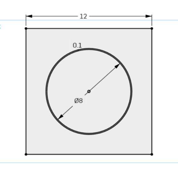
So, for example, fitting an 8mm cylinder in a part:
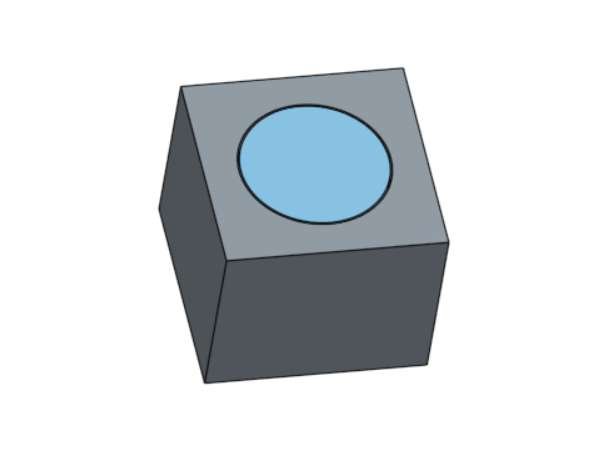
I have my nominal cylinder, but the hole I cut for it is 0.2mm larger in diameter. (There is a literal "offset" command in my CAD software that I use for this.) This is always my ballpark starting figure.
This tends to work for cylinder shapes in any orientation.
Continued in next post due to attachment limits or something.
Re: Openscad - parts that should fit into each other
It also applies to polygonal shapes in the XY plane.
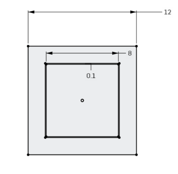
The particular problem here is that a FFF printer won't make those inner corners perfectly sharp. There will be some slop to them.
There are two options.
If you actually control the inner piece, just chamfer/fillet it:
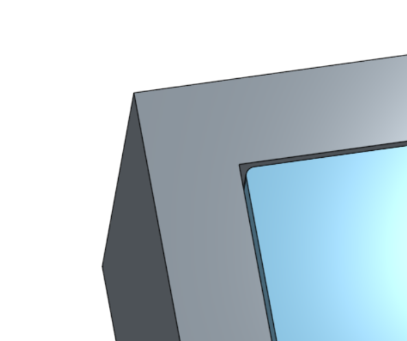
If not, then you'll have to compensate on the outer piece; I do something like this to keep the plastic out of the corner:
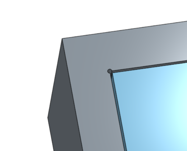
Basically it's a nearly imperceptibly small hole cut out of the corners.
It's a little different for polygons not in the XY plane, but I don't feel like getting into it.
Again these are all just variations on the same basic underlying rule for FFF printers; there are other cases to consider as well.
The unpleasant part is a lot of these modifications are a pain to do in OpenSCAD, which is why I've been using a different CAD tool. If you want to build stuff like this into your models, you have to really think ahead about things.
And again, to say there's no rule that can be formed out of all of this means either a designer has a haphazard design process, or maybe he's just boing coy while deliberately trying *not* to answer the question.
Re: Openscad - parts that should fit into each other
And BTW this is an example of a part has a lot of "fitting". I throw this on the printer when it's not doing anything else.

Re: Openscad - parts that should fit into each other
And again, to say there's no rule that can be formed out of all of this means either a designer has a haphazard design process, or maybe he's just boing coy while deliberately trying *not* to answer the question.
You said it yourself:
It's a little different for polygons not in the XY plane, but I don't feel like getting into it.
Yeah, it depends! On the model, on the nozzle size, on the settings, on the material, on how good your printer is printing...
Sure, we could be lazy and just say "add 0.2mm of clearance everywhere", as a starting point that works for me.
But you will find cases where 0.2mm is too much and cases where the parts won't fit.
My general advice if a tight fit is desired would be: do a test print with at least 0.2mm of tolerance, then measure the actual gaps you get and iterate.
(For fittings on the XY plane, you can print a 1 layer or 2 layers test very quickly, iterate to find the perfect fit. It is trickier on other planes, especially if bridges come into play where you will have some sagging etc.)
- Gab
Re: Openscad - parts that should fit into each other
do a test print with at least 0.2mm of tolerance, then measure the actual gaps you get and iterate
That's exactly what I usually do. 🙂 Sometimes the iteration is done by drill or file. 😉
@gz1: Thanks for detailed explanation. It strenghtened my opinion that there is actually no general rule to make required fit by first shot. Maybe this is the misunderstanding between us. Of course there is a general rule for quite good starting point and your explanation tells why and how.
Re: Openscad - parts that should fit into each other
For the interested, there is a discussion on Slic3r about the inner hole compensation:
https://github.com/alexrj/Slic3r/issues/3323
There is also a lot of knowledge in the Slic3r open issues on another topics:
https://github.com/alexrj/Slic3r/milestone/31
IMHO the inner holes could not easily be compensated for without extensive measurements due to the die swell effect:
https://en.wikipedia.org/wiki/Die_swell
I am still learning, but my impression is, that the pulling of the extrudate inside the small radii is the main reason why the holes get smaller than programmed.
Also note that not every slicer calculates the extrusions the same. AFAIK all the slicers but the Slic3r calculate with extrusions of rectangular crossections, only Slic3r applies a more involved model:
http://manual.slic3r.org/advanced/flow-math
Vojtech