Printing supports onto tape (not on the heatbed)?
Hi,
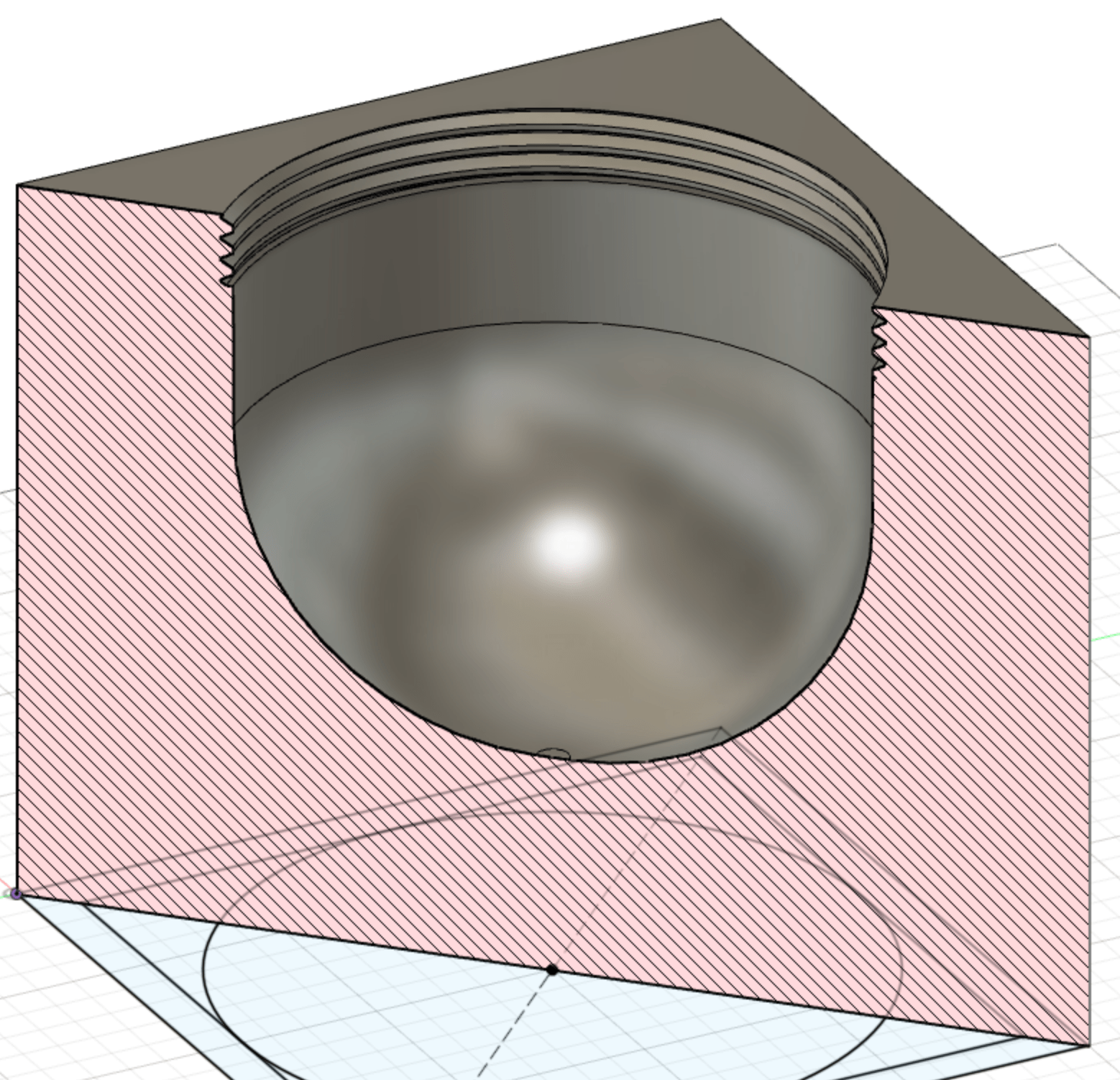
I have a project where I want to print a large 20cm cube with a 15cm circular threaded hole in one side (which a light will go in).
It will be printed with transparent filament, so marks on surfaces will show through in the final application.
I need the model printed in one piece to avoid seams and marks on the transparent printed lamp. My plan is to print with the top of the cube on the bed, and the large threaded hole on top -- in the final lamp, this hole will end up actually being the base. Any marks from support material on the base will not be as noticeable.
I'll need support for the overhangs which are the substantial amount of material around the threaded hole. To get the printing orientation clear, the first layers printed will end up being the top of the cube.
Being "transparent" and a lamp, I want the internal surfaces to be as clean as possible because remnant support bases or clumsy removal will be obvious in the end.
So I had a thought. When printing, after the first 10 layers (which will end up being the top of the lap), could I put some blue tape down or something like that, and hope that the base of the support material will adhere to it? Or tape with glue stick pasted on it? then at the end, I can just peel the tape off, leaving a clean surface. I'm going to do a dry run, but if anyone could give me a head's up that would be awesome.
I know printing on tape stuck to the bed/heatbed works, but in this case it won't be on the heatbed (it will be close to it, but it won't be 60C). Has anyone else had a similar experience in their own applications or got any other ideas?
Many thanks for your time.
best regards,
K
Best Answer by Kabammi:
Hi all,
Thanks for your help. After 3 days 2 hours or so (for the box), we have a good result.
We just printed the supports on the base (which ends up being the top). The thread printed just fine, and the base screws in perfectly.
Here's the print in progress. It got a bit dicey later on, with the extruder cables starting to clip the cube. I had to cable tie a hair tie to the hold the extruder cable bundle up and out the way (many many hours after this pic). Then there was a freaking layer shift right when the thick part of the base started, but it isn't too noticeable and I can probably shave it back if need be.

And the result, with the lights set in place in the base assembly, some cotton/polyester fluff popped in the box, and the base screwed in.
Lights turned on, and this is the result:
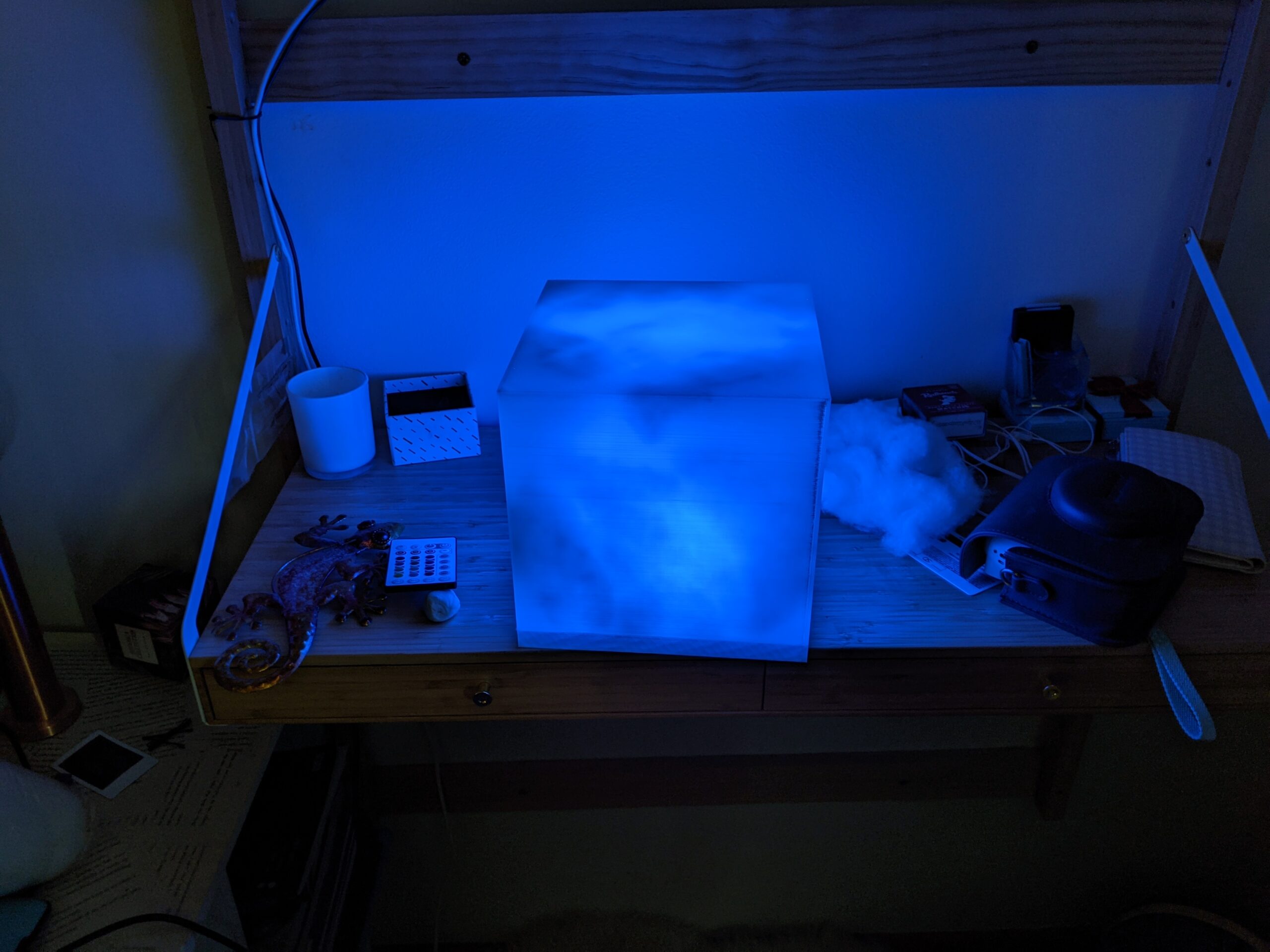
I love the shimmery effect which the cotton/polyester adds to it. It also mitigates the visual effect of the inevitable layer lines (but at 0.15mm they aren't too noticeable anyway).
Pretty damn good I reckon. The important thing is, my daughter is very happy with the result.
thanks for all your input.
K
It would be best if you could provide a Zipped up .3MF project file so we can see what your talking about, and the settings associated with it as well as the type of materiel your planing to use.
Good Luck
Swiss_Cheese
The Filament Whisperer
RE: thanks
It would be best if you could provide a Zipped up .3MF project file so we can see what your talking about, and the settings associated with it as well as the type of materiel your planing to use.
Good Luck
Swiss_Cheese
Hi Swiss_Cheese,
I'm using this flashforge transparent 1.75mm PLA filament purchased through Amazon.
https://www.amazon.com.au/gp/product/B07Y7R4RW6/
The .3MF is also attached.
I'm using a MK3S with "0.15mm QUALITY" print settings. If you look at the paint on support tool, you'll see that I've slopped support blockers on the thread and support enforcers using the paint-on automatic angle detector. It's put supports underneath the base but that doesn't matter. 20% Cubic infill, which really only affects the base because the other 5 walls are solid. There might be some other settings I made, but they'll be in the .3MF
Many thanks.
cheers,
K
re
oh, and you might see that I've added a M601 Pause at 2mm, where I thought I could put some tape on, before continuing the print.
@kieran-s4
In the past I have modeled in my own supports, paused the print and added in a layer of PVA glue to act as a release for the supports, applied with a Q-Tip and I've had good success with this technique, however after looking at your model I think this may be the least of your issues, I would expect that you will be dealing with warping and bed adhesion issues far before you ever get to the point of having to deal with support removal.
If you do manage to get this to print beyond warping, you may find that you want more support under the Bridging area of the print to get a cleaner result and you may also want to model that support in manually for better more easily removable supports. Tape will only cause issues with height range and would most likely compromise the print. PVA glue or a layer of TPU added in before the supports and after the contact layer will in my experience be the best way to get a clean release with a smooth result.
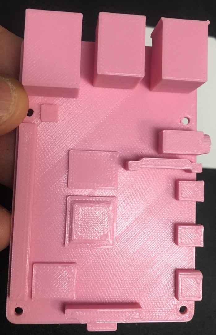
The blue that you see is a single layer of TPU printed on top of a modeled PETG support.
the White PETG you see is all Bridging accept for the small tab.

they printed together with a material change and a pause then I applied PVA glue with a Q-tip to aid with separation

I developed this technique to produce a model of a Ras Pi that had two clean sides.
Top
Bottom
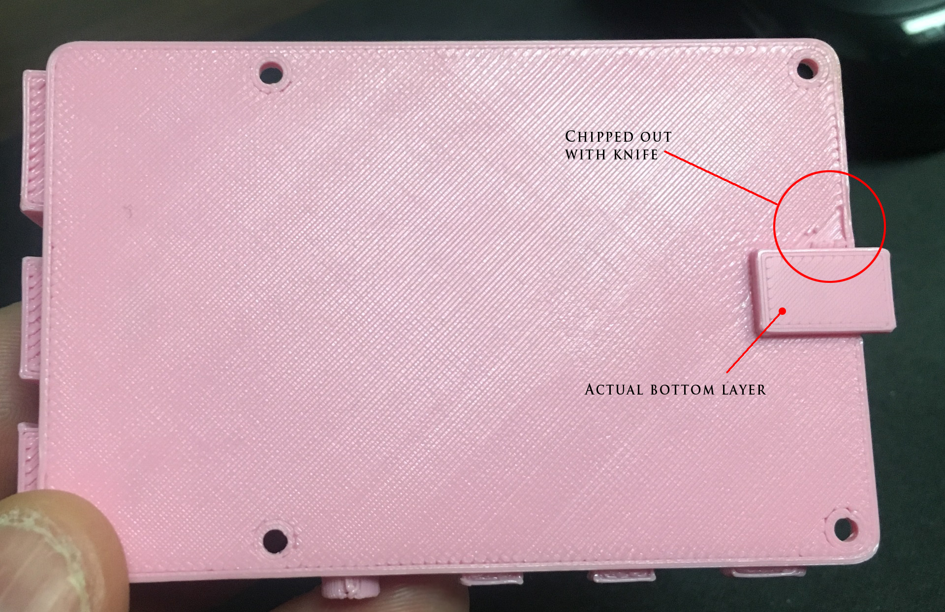
and have used it several times since in different situations to produce bridging that is strong and pressed together with a similar appearance to a top layer.
Keep us informed of your progress, I'm interested to see how this goes.
Good Luck
Swiss_Cheese
The Filament Whisperer
Have you considered optimizing the design for easier 3D printing?
[...] I'll need support for the overhangs which are the substantial amount of material around the threaded hole. To get the printing orientation clear, the first layers printed will end up being the top of the cube.
Some observations:
- This looks like a part you've designed. As such, you can easily make design changes.
- The depth for the lamp assembly to screw into is roughly 20mm deep. The internal angles for the bottom (printed on top) are all 90° with no chamfer or fillet to improve strength where the walls meet.
- With the exception of the infill required to support the top surface, the model is hollow.
With this in mind, I'd add a chamfer or angled internal support that reaches from the walls inside the box to the bottom (top of print) around the lamp socket. That will both eliminate the need for support completely (thus improving your internal surfaces and the specific problem you've asked about) and improve the overall strength of the assembled unit. Something like this:

I've attached a dummied up STL to show the approach. Even better would be a 2 part design:
- The base with the threaded hole. Print this flat on the bed with no support required.
- Print the clear dome as an inverted box (solid surface down) sized so it slips over, clips, friction fits, or screws onto the base. Again, print this flat on the bed with no support required.
This would be much easier to print and repair in use.
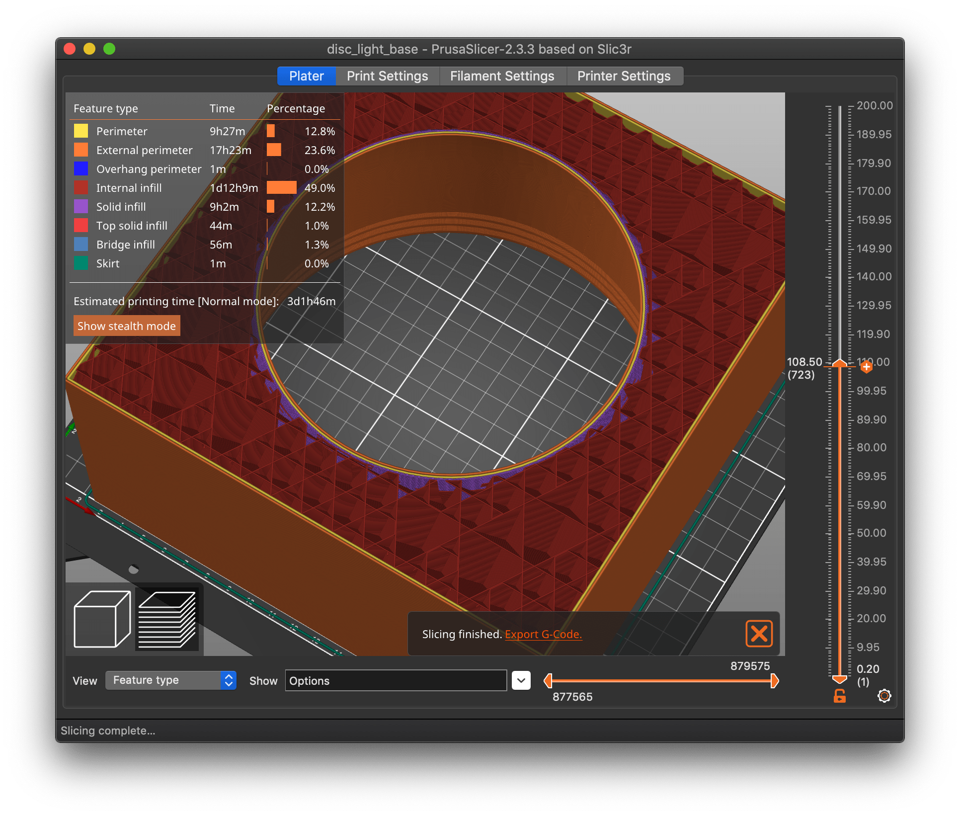
Another concern is print time. This is going to be a miserable print with a 0.4mm nozzle.
- I'd definitely pick up a 0.6-1.0mm nozzle for this size of print. Your current settings show 2 perimeters @ 0.45mm with a 2mm? thick wall, so you are getting some gap fill. With a wider nozzle, you could print that same wall thickness with 2 TOTAL perimeters, thus saving printing 2 perimeters plus gap fill. This will tremendously speed up your print time and likely improve transparency. This change alone reduces the print time estimate from 3d5h to 1d14h.
- Higher layer heights can also improve transparency. With a 0.8mm nozzle, you can easily print at 0.4mm layer heights. This, along with the wider extrusions, reduces the print time estimate to just under 24h. The revised STL will print in under 18h (slicer estimates).
- You didn't mention what sort of lamp you plan on using, but without some ventilation, you're likely to get quite a bit of heat build-up inside that box. Consider adding some vents. If nothing else, be sure to print it with a filament that can withstand higher temperatures.
- Do you need to add a hole or channel to route wiring?
Your color change approach is novel and interesting, but there are ways to print this particular part with a lot fewer headaches! Are these going to be arrayed into a larger display, or is each one going to be a stand-alone? I'm curious what sort of light fixture you're planning to screw in there. It's a big one!
RE: My daughter is driving this design.. 🙂
Hi Bobstro,
Thank you for your input! Yes, it's my design. The end product is supposed to resemble a Marvel Tessaract. There will be 4 submersible-style RGB lights in it, all sealed, all battery-powered, operable by remote control. They're shaped like pucks, my daughter bought them and wants/demands to use them.
https://www.amazon.com.au/gp/product/B07JPBZRYV
So you need to be able to get into the cube when it's finished to change batteries every now and then. They are a bit heavy so I came up with a bit of a monstrosity to hold them in place and angle them correctly. See attached. That model screws into the base, no cooling or air flow is necessary I think.
I looked at chamfer and filleting, but it creeps so far up the walls, and it really shows through the transparent walls quite seriously (lets call it what it is in reality -- looking at your Flashforge - translucent!). This really is a different beast to opaque filament printing. I wouldn't hesitate to fillet/chamfer normally. I test printed a wall with infill running to the inner face, and you can see everything. So I want to (at least on 5 sides), make it as even as possible.
I'm currently printing the 3mf I first posted, I just split the model in Prusa Slicer towards the top, and I'll see how well the bridging works off the small amount of support material in that 3mf model. It's actually just past bridging now, and it's looking remarkably good at the moment, so I'll see how it finishes up.
I do take your point about the time. I realise it was 3 and a bit days, which is a long time for things to play up. I could be in for a world of pain. I do have a 0.6mm nozzle. However I wanted to reduce/minimise layer lines if that's possible. Hence why I'm using 0.15mm layer thickness. Perhaps my understanding of how that works is just wrong though.
The slip-fit rather than screw in base was a big consideration. However, I couldn't work out how I could make something that wouldn't wear out over time, or be easy to remove. The LED lights are not light in mass.. and my daughter wants to be able to pick it up. Yes the base is super thick, and that was by design to give the lights something to really mount to. As you'll see in the attached 3mf.
I'll probably spend 3 and a bit days printing it, and she wont like the thickness of the base and I'll have to thin it out and start again, or rethink the whole strategy!
Fun with big cubes
[...] The end product is supposed to resemble a Marvel Tessaract. There will be 4 submersible-style RGB lights in it, all sealed, all battery-powered, operable by remote control.
Ah, gotcha. I thought it was going to be one of a collection of "pixel cubes" something like this:
![]()
So you need to be able to get into the cube when it's finished to change batteries every now and then. They are a bit heavy so I came up with a bit of a monstrosity to hold them in place and angle them correctly. See attached. That model screws into the base, no cooling or air flow is necessary I think.
OK, so no external cable is required. You just unscrew the holder and change the pucks, correct? Neat design.
I looked at chamfer and filleting, but it creeps so far up the walls, and it really shows through the transparent walls quite seriously (lets call it what it is in reality -- looking at your Flashforge - translucent!). This really is a different beast to opaque filament printing. I wouldn't hesitate to fillet/chamfer normally. I test printed a wall with infill running to the inner face, and you can see everything. So I want to (at least on 5 sides), make it as even as possible.
If this is a free-standing cube, that makes sense.
I'm currently printing the 3mf I first posted, I just split the model in Prusa Slicer towards the top, and I'll see how well the bridging works off the small amount of support material in that 3mf model. It's actually just past bridging now, and it's looking remarkably good at the moment, so I'll see how it finishes up.
Unfortunately, supports for horizontal surfaces remain a weakness in PrusaSlicer. The next release is supposed to significantly improve supports. For now, here's a comparison I did of supports for horizontal surfaces printed with ideaMaker, Simplify 3D, PrusaSlicer and Cura:

I do take your point about the time. I realise it was 3 and a bit days, which is a long time for things to play up. I could be in for a world of pain.
If this is a one-off, it's not as much of a concern. I thought you were doing a larger batch.
I do have a 0.6mm nozzle. However I wanted to reduce/minimise layer lines if that's possible. Hence why I'm using 0.15mm layer thickness. Perhaps my understanding of how that works is just wrong though.
A few thoughts:
- With a part this large, a bit of post-processing (wet sanding) might give you the best, most translucent results. That opening is large enough, you can probably get inside as well.
- There was a productive discussion on improving transparency in the "How to print glass" thread that might be of interest.
- I found that clear/translucent walls really benefit from a dip with acrylic floor wax. This is an old scale modeler trick for improving aircraft canopy and car windshield appearance. Doubly so if you do any wet sanding. See examples in the "glass" thread.
The slip-fit rather than screw in base was a big consideration. However, I couldn't work out how I could make something that wouldn't wear out over time, or be easy to remove. The LED lights are not light in mass.. and my daughter wants to be able to pick it up. Yes the base is super thick, and that was by design to give the lights something to really mount to.
This is a fun project. I am always a bit jealous since my boys were well out of the house before I got my first 3D printer. Man, the money and frustration I could have saved!
If you want to stick with a single big print, I'd spend some time looking at printing with the opening down. Supporting circular openings is always tricky, and you're going to want those threads to print cleanly. Supports building up from the build plate, through the opening, and up to a single flat top surface is probably going to give you a better result. Your tape or @swiss_cheese 's suggested paint-on technique would probably be easier to apply to a single support surface as well.
I'll probably spend 3 and a bit days printing it, and she wont like the thickness of the base and I'll have to thin it out and start again, or rethink the whole strategy!
More thoughts:
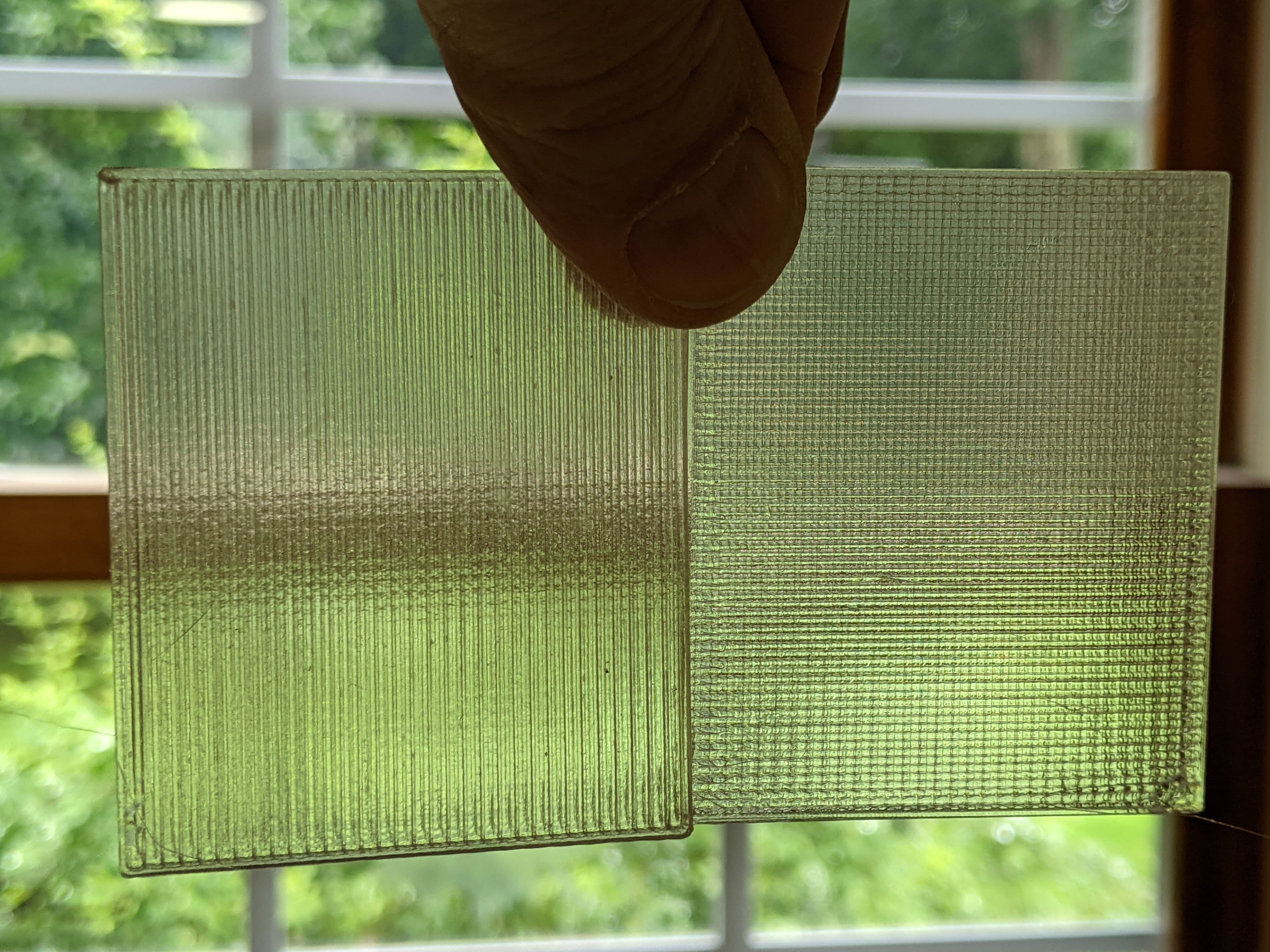
Printing each wall all as a flat panel and assembling after printing (e.g., some small support cubes in corners) might be best for clarity. In the glass thread, it was quickly apparent that achieving good clarity with any sort of vertical surface is difficult. Depending on the diffusion you want, the new Monotonic infill (sample on right) is worth a look:
Looking at some pics of the cube prop from movies, it has a "cloudy" internal appearance. You might be able to get an interesting pattern by making infill your ally and THICKENING the walls. This would reduce if not eliminate the top layer printing challenge and different infill patterns produce interesting light diffraction patterns. Something like this for the design:
And possibly Adaptive Cubic infill:
Use a similar infill pattern on the puck stand and it might improve the illusion of being a continuous cube.
This is a fun project. Keep us updated on your results!
Movable LED pucks?
A couple more quick thoughts:
- If you make the puck stand a print-in-place insert into the screw-in base, the lighting pucks can rotate internally as the cube is moved. Since the pucks are stand-alone rechargeable units, there's no/less worry about cabling. Bonus points for a gimbal that allows one or more pucks to rotate freely.
- The 3D Honeycomb pattern looks like it'll generate an interesting diffraction pattern. Gyroid is worth a look too. 5% infill looks promising.
- Probably better to print threaded side up if going with the thick walls. It drops print time quite a bit.
@kieran-s4
You might want to consider printing the 5 sides using Vase mode Then changing your Base that holds the batteries and LEDs to a square and design a snap-fit that will hold it closed.
you would print the lid (the 5 sides) top down on the bed this would give you a more translucent look needing no supports and give you the best chance of not warping off the bed, I thought I saw you mention that you had a 0.6 nozzle handy and that would help to provide a strong wall for the single perimeter print.
Just a thought,
Swiss_Cheese
The Filament Whisperer
edit time expired
You could also print the puck holder separate and glue the parts together with a good cyanoacrylate.
The Filament Whisperer
re
so no external cable is required. You just unscrew the holder and change the pucks, correct? Neat design.
Yes that is correct. That way it can be picked up, and the base is well fixed and won't fall out. Unscrew the base and replace batteries on the pucks, or whatever is necessary.
I'm currently printing the 3mf I first posted, I just split the model in Prusa Slicer towards the top, and I'll see how well the bridging works off the small amount of support material in that 3mf model. It's actually just past bridging now, and it's looking remarkably good at the moment, so I'll see how it finishes up.
Unfortunately, supports for horizontal surfaces remain a weakness in PrusaSlicer. The next release is supposed to significantly improve supports.
I don't think I'll need side supports.
My print of just the top 4cm worked very well. The bridging worked extremely well, far far better than I had ever expected. The 4 walls plus honeycomb supports stuck down really well, and the honeycome supports came off extremely easily; off in 5 seconds, clean removal.
I do take your point about the time. I realise it was 3 and a bit days, which is a long time for things to play up. I could be in for a world of pain.
If this is a one-off, it's not as much of a concern. I thought you were doing a larger batch.
We'll see how many iterations we have to go through to get the final product.. 😉 But yes, it'll be a one-off.
I do have a 0.6mm nozzle. However I wanted to reduce/minimise layer lines if that's possible. Hence why I'm using 0.15mm layer thickness. Perhaps my understanding of how that works is just wrong though.
A few thoughts:
- With a part this large, a bit of post-processing (wet sanding) might give you the best, most translucent results. That opening is large enough, you can probably get inside as well.
- There was a productive discussion on improving transparency in the "How to print glass" thread that might be of interest.
- I found that clear/translucent walls really benefit from a dip with acrylic floor wax. This is an old scale modeler trick for improving aircraft canopy and car windshield appearance. Doubly so if you do any wet sanding. See examples in the "glass" thread.
Thanks for that. I see in that Glass thread the results are really nice, but it emphasises the layer lines even more. I want to avoid that if I can.
The slip-fit rather than screw in base was a big consideration. However, I couldn't work out how I could make something that wouldn't wear out over time, or be easy to remove. The LED lights are not light in mass.. and my daughter wants to be able to pick it up. Yes the base is super thick, and that was by design to give the lights something to really mount to.
This is a fun project. I am always a bit jealous since my boys were well out of the house before I got my first 3D printer. Man, the money and frustration I could have saved!
My daughter is very arty, is very good at painting, drawing and sculpture. I'm trying to get her to see the possibilities of using 3d printing to expand her toolkit. So I really want it to work.
If you want to stick with a single big print, I'd spend some time looking at printing with the opening down. Supporting circular openings is always tricky, and you're going to want those threads to print cleanly. Supports building up from the build plate, through the opening, and up to a single flat top surface is probably going to give you a better result. Your tape or @swiss_cheese 's suggested paint-on technique would probably be easier to apply to a single support surface as well.
Well, my test print with the hole at the top overnight worked really well. As I said, super clean bridging (I should have taken a video to show you), and the thread printed beautifully. The base (which I've already printed) screwed in the first go. So I know I can print hole up now.
I should be scientific about this and make a short version of the cube now, and see what printing the supports does to the inner surface of the cube. Perhaps it won't be noticeable.
I'll probably spend 3 and a bit days printing it, and she wont like the thickness of the base and I'll have to thin it out and start again, or rethink the whole strategy!
More thoughts:
Printing each wall all as a flat panel and assembling after printing (e.g., some small support cubes in corners) might be best for clarity. In the glass thread, it was quickly apparent that achieving good clarity with any sort of vertical surface is difficult. Depending on the diffusion you want, the new Monotonic infill (sample on right) is worth a look:
Yes, that is a definite consideration and definately might end up being the final answer to this. My daughter is considering putting cotton wool around the pucks, filling the cube with it, to give it a mysterious diffracting appearance. TBA though, it might block too much light.
But the right-hand print there looks on the money I reckon.
Looking at some pics of the cube prop from movies, it has a "cloudy" internal appearance. You might be able to get an interesting pattern by making infill your ally and THICKENING the walls. This would reduce if not eliminate the top layer printing challenge and different infill patterns produce interesting light diffraction patterns. Something like this for the design:
Now that is something I hadn't considered. Very interesting.
And possibly Adaptive Cubic infill:
Use a similar infill pattern on the puck stand and it might improve the illusion of being a continuous cube.
That's true. More to think about.
This is a fun project. Keep us updated on your results!
I certainly will.
I'll do a test run to see how printing supports affects light propagation through it. If it's okay, I might try printing it. I also fear that the base will end up being too thick, but I won't know until it's all together.
thanks again,
K
RE: result
Hi all,
Thanks for your help. After 3 days 2 hours or so (for the box), we have a good result.
We just printed the supports on the base (which ends up being the top). The thread printed just fine, and the base screws in perfectly.
Here's the print in progress. It got a bit dicey later on, with the extruder cables starting to clip the cube. I had to cable tie a hair tie to the hold the extruder cable bundle up and out the way (many many hours after this pic). Then there was a freaking layer shift right when the thick part of the base started, but it isn't too noticeable and I can probably shave it back if need be.
And the result, with the lights set in place in the base assembly, some cotton/polyester fluff popped in the box, and the base screwed in.
Lights turned on, and this is the result:
I love the shimmery effect which the cotton/polyester adds to it. It also mitigates the visual effect of the inevitable layer lines (but at 0.15mm they aren't too noticeable anyway).
Pretty damn good I reckon. The important thing is, my daughter is very happy with the result.
thanks for all your input.
K