From bad to worse....
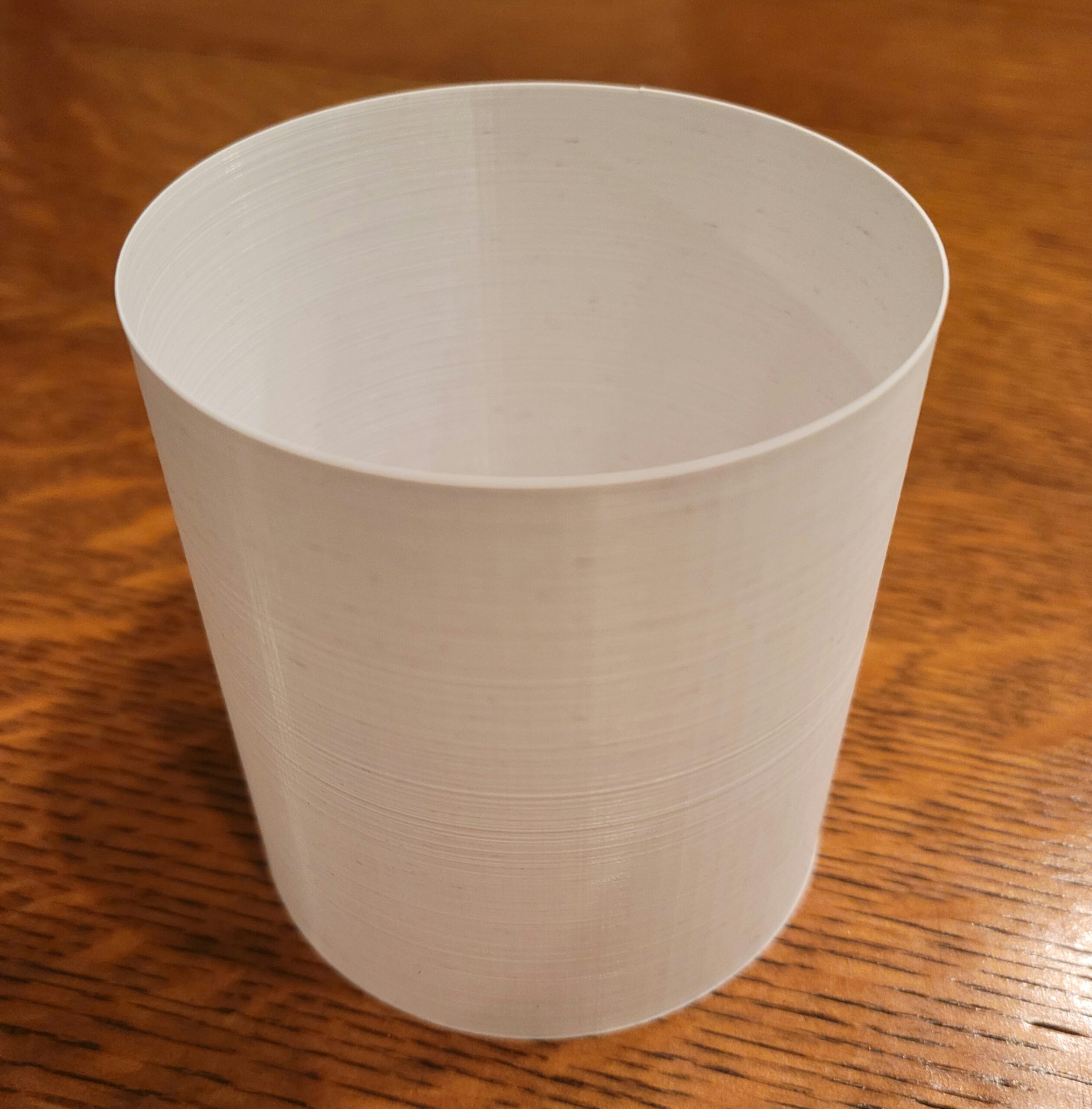
Trying to print a one-perimeter thick flexible filament cylinder in vase mode, 70 mm in diameter, 75mm tall, on my MK3. First attempt was actually not too bad (on left in photo), but has voids starting at 10.9mm, then recovers, voids again at 21.1mm through 23.1, recovers again, gets really bad at 43.3mm and above, but the top 7.5mm is fine. (Layer thickness is 0.1mm.) The second attempt started to fail at 30.5mm, at which point I increased the flow rate from .95 to 1.05. At this point I had to discontinue watching. When I returned, I found the failed mess on the right. Filament is Filatech FilaFlex40, printing at 240C. (range given on spool is 220C to 240C). Made sure filament was unspooling without any back-pull or binding. Z-axis screws and X-Y belts are clean, smooth rods properly lubed. Using a 0.4mm nozzel but measured finished shell thickness is 0.6mm. Should I try a 0.25mm nozzle? Higher or lower temperature? Different flow factor? Other ideas? The herringbone "ringing" I can live with but not the voids.
Hear ye, Hear ye! Step right up folks and get your Government salvation here! Less than $.002 per word! Amazon.com/dp/B0B8XMMFP4
RE: From bad to worse....
I’m afraid I don’t have experience with this specific filament but for prints in vase mode I generally look at 3 settings that can have a big impact on print results.
1. Increase the layer width above the stock setting in small increments until you start to see the results you want.
2. Increase the layer height to 0.15.
3. Decrease the print speed by 20-25% from default.
Good luck, I hope you get it sorted. Keep us posted.
Cheers
Vase mode flex is always going to be a testing print...
If you have one, try a larger nozzle and slow right down, a bigger layer height has a better chance too.
Cheerio,
RE: From bad to worse....
For the 3rd attempt (pictured), and before having read the above two responses, I lowered the speed to 75%. There was a marked improvement, but still some vertical "banding" and smaller, but regular voids. I started a 4th trial but stopped it at a height of 11.3mm to increase the layer thickness to 0.15mm as suggested and reduce the speed even further. I noticed that this shorter band has a much smoother interior surface (desirable) as distinguished from the exterior herringbone pattern (ringing). What causes this difference? The second attached photo attempts to show this but it depends on light impinging angles to see clearly.
For technical reasons (in the use of the item) I can't use a larger nozzle. It's already producing a 0.6mm wall thickness using the 0.4mm nozzle, and I really need a finished thickness closer to 0.3mm, which is why I wondered about using a 0.25mm nozzle. In any event, trial #5 is currently printing at 50% speed and a few other minor tweaks. Stay tuned.
Hear ye, Hear ye! Step right up folks and get your Government salvation here! Less than $.002 per word! Amazon.com/dp/B0B8XMMFP4
RE:
Ok, this one looks a lot better (no holes or voids) but has other issues. At 3+ hours to print (50% speed), ugh! I need 200 pieces. Not sure if the slower speed is the culprit, but the wall thickness came out even thicker at 0.7mm. This may preclude it working properly in a sub-assembly, which I have not had a chance to test yet. Very oddly, the first 3.4mm of height is completely smooth, showing only a continuous spiral with a wall thickness of 0.5mm, closer to what I need than earlier tests. But at that height, it abruptly starts "ringing" with the herringbone pattern which apparently adds 0.2mm to the wall thickness. Still to be explained is why the inside of the cylinder looks and feels smooth; the herringbone is only on the outside.
I did make this observation: At this low gantry speed a cyclical low-amplitude vibration can be felt in each of the five stepper motors, although the vibrations are not "in sync" among the motors. The amplitudes rise and fall 4 times during one circuit of the nozzle. I'm attributing this to the pulses applied to the motors which is palpable due to the very slow speed. The fact that they are out-of-phase with each other may explain the psudo-random herringbone pattern. Does this seem to be a fair assessment of what is happening? Is this fixable? Is there such a thing as analogue motors in this application? 
Hear ye, Hear ye! Step right up folks and get your Government salvation here! Less than $.002 per word! Amazon.com/dp/B0B8XMMFP4
RE: From bad to worse....
Can you upload the 3mf?
Formerly known on this forum as @fuchsr -- https://foxrun3d.com/
RE: From bad to worse....
3MF attached. Some refinements I made are a filament diameter of 1.72mm (measured) vs. 1.75.. (default) and "Classic" perimeter generator vs. Arachne (based on the context explanation of the two).
Hear ye, Hear ye! Step right up folks and get your Government salvation here! Less than $.002 per word! Amazon.com/dp/B0B8XMMFP4
0.3mm thick flex tubes are very unlikely to be self-supporting above 20-30mm ... your description of defects increasing with height is what I would expect to see - the higher you get the more the part deforms under pressure and vibration.
Could you print a 0.3mm flat sheet then roll around a former and glue?
Are all these parts to be the same diameter? If so cutting a length of tube would be easiest; for flexibility but not much stretch a roll of polyethylene layflat tube might suit, the stuff sold for heat sealing into custom length bags is readily available from packaging suppliers in various weights, or for a just few buy a pack of plastic bags and cut off the ends.
if you can't get tubing then consider repurposing cylindrical balloons or latex gloves.
To manufacture from scratch dip a cold metal rod into a pot of molten latex and peel it off when set. Or pour flexible mastic or filler over a former and peel when set.
Your file-name is intruiging, what are you making?
Cheerio,
RE:
Well, except for the early spectacular spaghetti failure, these cylinders ARE self-supporting up through 75mm and probably would have gone a lot higher. It’s the inconsistency of the layering, the voids and the ringing that are the problem(s).
The use for this cylinder is difficult to describe, but I’ll try. A company by the name of Kikkerman manufactures a DIY music box that uses strips of card stock weight paper into which users punch holes using a special punch, reminiscent of the old player piano rolls. The strips are fed into the music box mechanism and a hand crank then advances the strip through the tuned teeth of the movement to play music. The paper strip is 75mm wide and can be as long as you wish. The strips are 0.012” (0.31mm) thick and cannot deviate from that thickness much before they will either bind up or fail to be advanced by the pressure rollers
My application replaces the paper strip with a finite length (circumference) cylinder which, when inserted into the mechanism, will play a short segment of a song over and over again as long as the hand crank is turned. The cylinder must be white in color to simulate piano roll paper because it will be visible in a miniature scale (about 1:10) piano shell. It has to be flexible enough to transport through the mechanism but rigid enough to be able to “turn” the small spoked wheels that poke through the punched holes that then pluck the tuned teeth. So thin, balloon type latex will not work. Neither will forming a cylinder out of the same kind of paper with a glued lap joint work because the double thickness at the joint will hang up. A “butt” joint would still need some kind of adhesive tape overlay, adding thickness and unlikely to stay together for many cycles. Cosmetically, the appearance of the joint would not be ideal. Believe me, I have tried to source cylinders with all of the required parameters from about 20 suppliers and nobody can do it at any reasonable per-unit cost. The material also needs to be laser cutter compatible because that’s how I plan to cut the holes. So I got the idea to print these myself. Diameter and height are easy to control, it’s the thickness consistency that’s turning out to be problematic.
The attached photo shows the two most recent trials, backlit with a flashlight to bring out details.

Both were printed with the same settings but #7 is noticeably worse, in terms of thickness consistency, than #6. The ONLY change I made between the two trials was to position the filament supply reel on a low-friction ball bearing caddy (actually a Mini caddy) rather than the normal MK3 top frame-mounted “T” arm. If anything (and counter-intuitively), this resulted in less consistency and more “banding” in the wall thickness, along with some voids.
So, the next thought I had was, if the 0.4mm nozzle is consistently producing uneven (but thicker-than desired) wall thickness, why not try a smaller nozzle? I now had a dilemma because neither of my MK3s are configured for a smaller nozzle. Only my Mini has the interchangeable E3D nozzle system, and I had never tried a flexible filament on the Mini. I have never had a good feeling about the ability of Bowden tube extruders to properly handle flexible filaments. It just seems to me that trying to “push” a chain (or, if you prefer, a rope) is, in the physics sense, bound to fail. I was not disappointed in that assumption. I managed to install the 0.25mm nozzle on the Mini and the filament loaded up to the hot end, but then would go no further, much less actually extrude. What a disaster. Now, the filament would not unload and I had to completely disassemble the extruder in order to get it out. Not surprisingly, the filament had "bunched up" at the hobbed gear. Is it even possible to print with a flexible filament on the Mini? At that (or any) nozzle size? Has this topic been discussed anywhere?
So THEN I got the idea that MAYBE If I am able to get the wall thickness down with the 0.25mm nozzle, then MAYBE a PLA cylinder would turn out to be flexible enough to work with the music box movement. THAT trial is printing as I type this and looks good so far. Results later.
Hear ye, Hear ye! Step right up folks and get your Government salvation here! Less than $.002 per word! Amazon.com/dp/B0B8XMMFP4
RE: From bad to worse....
Interesting project! I would think PETG would be more flexible than PLA for your use case. Maybe make your next trial part in PETG? Idk how either material will laser cut.
Good luck!
Cheers
RE:
 Well! The 0.25mm print vase mode LOOKS pretty dang good! Pretty consistent wall thickness at 0.3mm, a little under spec. Both inside and outside are supprisingly smooth with no herringbone ringing. I am concerned about layer-to-layer adhesion as it seems like it may "unravel" with repeated cycles through the mechanism. It will be a couple of days before I will be able to conduct a "live" test. There are some very small random voids, but look to be inconsequential in comparison with the soon-to-be-punched holes that actuate the notes.
Next trial will be with PETG in non-vase mode to see if layer adhesion improves and thickens the wall a bit. I also picked up some white resin which I will try in my SLA printer (AnyCubic). I'm hoping that in that thin of a wall thickness, it will be at least as flexible as the PLA, and layer adhesion should be sufficient. Does anybody know if anyone manuactures an SLA resin that produces "flexible" (~Shore A-40) prints?
Hear ye, Hear ye! Step right up folks and get your Government salvation here! Less than $.002 per word! Amazon.com/dp/B0B8XMMFP4
A fascinating little Jaquard mechanism like a tiny fairground organ ...
Looking at the advert - the thickness of the music ribbon seems to be dictated by the sprung metal throat and the diameter of the plastic idler.
It should be possible to ease the throat and print a lower diameter idler; that way a thicker ribbon, much easier to print, should work.
After all, you were already going to have to disassemble to fit the looped ribbon, might as well experiment a bit at the same time.
As an additional fun exercise, printing the ribbon with music aleady encoded should be possible.
Cheerio,
RE: From bad to worse....
Looks like you’re making good progress.
I would try the PETG print in vase mode as well. Unclear why you would do otherwise?
Cheers
RE: From bad to worse....
Very perceptive of you on how the mechanism works. Not sure I could have deduced the details you have from the illustrations. I, of course, have the benefit of having mechanisms in hand, so that makes it much easier to assess mechanically. Indeed, I do have to partially disassemble it to insert the continuous band vs. the two-dimensional strips. It would take a major re-engineering effort to change the pressure wheels and plate seperation to accommodate a web thickness other than the supplied strips. The friction (or lack thereof) of the web material is also crucial to correct movement. I'm also hoping to find a way that I can program the note-producing holes into the model file so I don't have the post-printing task of laser cutting them, which has its own issues, including needing to have a rotary chuck as a substitute for the laser's Y axis. I happen to have access to one of those, but I would like to avoid it if possible, and have the holes print as part of the cylinder. It will be a nifty project if I can pull it off.
Hear ye, Hear ye! Step right up folks and get your Government salvation here! Less than $.002 per word! Amazon.com/dp/B0B8XMMFP4
RE: From bad to worse....
Well, the 0.4mm nozzle in vase mode is giving a wall thickness that is too thick and the 0.25mm nozzle is too thin. The trial currently printing is PLA non-vase with the 0.25mm nozzle, aiming for a sweet spot of ~0.4mm wall thickness. Will see what happens. PETG is next. Anxious to try a resin print also.
Hear ye, Hear ye! Step right up folks and get your Government salvation here! Less than $.002 per word! Amazon.com/dp/B0B8XMMFP4
RE: From bad to worse....
I didn't read everything here, I did look at the project file, and I noticed it was set for spiral vase.
Has anyone suggested simply making a 70 X 70X 75 cylinder (not a tube), setting the extrusion for external perimeter thickness to whatever the tube wall thickness should to be, resetting the Slice Mode to "Regular", and turning off elephants foot compensation, or at least not having it set to 0.4?
RE: From bad to worse....
Interesting, I'll try that approach.
Hear ye, Hear ye! Step right up folks and get your Government salvation here! Less than $.002 per word! Amazon.com/dp/B0B8XMMFP4