Complex Part Design
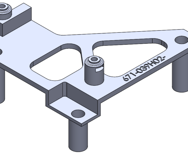
I am reaching out to you today looking for some assistance with printing the part attached to this thread. I am using Hatachbox PLA and 3DXSTAT PVA material. The upper and lower columns keep detaching. I have tried just using PLA as supports as well as Soluble Interface.
Look forward to your reply
RE: Complex Part Design
Do they detach when printing - or when the part is in use?
In other words, is this a printing problem or a design problem?
Pictures of the failed break surface would be useful.
Cheerio,
RE: Complex Part Design
@diem
I thought about that when i left work. I should included the pictures of the part. I will have to do that in the morning when i go back in, sorry.
The upper and lower columns snap off at the contact point on the main body. I tried to upload the .stl for it but it failed so i guess you can't do that. I can attach the solidworks file if anyone is interested.
RE: Complex Part Design
If I made that part out of metal, the parts would bend or snap off at the same place if enough stress were placed.
For a no-design-change strength improvement, here are some things to think about
Infill - different infills have different strength characteristics. Gyroid is a light weight zero strength item. Honeycomb is very strong.
Increase perimeters - the more perimeters, the more layers are bonding between the flat part and the round part.
From there, we get into how to design a post that doesn't snap off at the flat spot. Fillet's will help a ton.
RE: Complex Part Design
@yngeinstn
Zip any files you want to send, .zip files are allowed.
As @dan-rogers suggests, fillets are a simple way to strengthen the fix point of a narrow part, IF space is available then making the contact end of each column conical should help.
The problem is that you have only layer-adhesion to provide lateral strength here, more perimeters might help but the strongest method would be to redesign the chassis with sockets and print the columns horizontally to glue in place afterwards.
Cheerio,
RE: Complex Part Design
I agree with the enough stress however in this case, i could almost breath on it and it would come off.. Fillets is a good idea i will contact the designer of the part. I have the max number perimeters allowed.. I will definitely try a different infill.
RE: Complex Part Design
@diem
Thank you for the inputs. I since i have the Solidworks part file i will make some indiscriminate design changes myself. I have to admit designing a part that isn't flat on one side has proven to be tricky...
RE: Complex Part Design
@yngeinstn
If you can save the part out as .OBJ or .STL (preferably .OBJ) you then have to zip the file up before the server will accept it.
also some images of the problem, as mentioned before would be helpful, and I would like to mention that the embossed part Number shown in the image you did post would turn out much better when produced via FDM/FFF if it was recessed instead, if that's a option.
regards
The Filament Whisperer
RE: Complex Part Design
@yngeinstn
Can you slice the part in two, horizontally, through the centre of the plate thus gettng two parts that are much easier to print and then glue them together afterwards?
Cheerio,
RE: Complex Part Design
@diem
I am not sure that is an option. I am going to assume this is used for some Test Fixture. I can ask.
RE: Complex Part Design
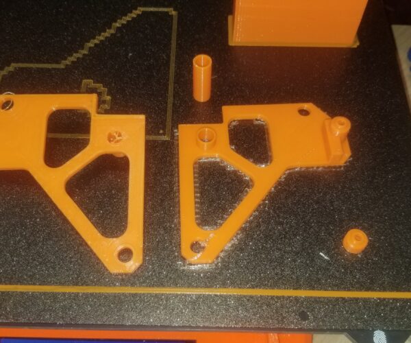
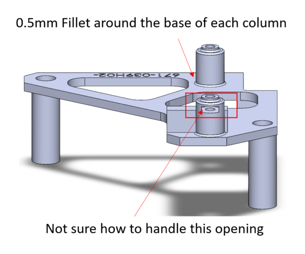
As promised however, here is a picture of the last two attempts to print this. I have also attached the .zip file with the part file (if anyone has Solidworks), an .obj file (post slice), an .amf file (post slice) and the .stl file. I also went to the part file in Solidworks and added a 0.5mm fillet on all of the columns
If you look at the 2nd picture I made a note where the opening is on that column. Previous to the .obj and .amf export, I just used 0.20mm Soluble Interface with supports "On Build Plate Only". This slice is supports "Everywhere".
I want to give this another go but I think i will wait to hear back from some of you before it do.
Again, appreciate the help.
dh
RE: Complex Part Design
Had to split up the files due to size limitations
RE: Complex Part Design
0.5mm fillet is only one extra printed perimeter.
If you're doing that much supporting, try tilting the part at 45 degrees; be sure to cross the stress direction. It will require a little more support but you will gain some lateral strength as the lay of the filament vectors into the Z direction.
The big drawback will be the need for even more purging to prevent soluble filament remnants being incorporated into the structure and weakening it.
Cheerio,
RE: Complex Part Design
@diem
Thanks for the reply .. You think you can slice it to show me what you are referring to? I purge a lot when i using the PVA so that is taken care of
RE: Complex Part Design
@diem
Thanks for the picture. Quick question, how do you NOT use the PVA on the 1st layer? I can't seem to figure out that setting. I wants to put PVA down first
RE: Complex Part Design
Try less cooling and or slower printing speeds, if the layers are parting, the temperature was too low for the layer to melt into the previous layer properly.
Lots of cooling gives you very nicely detailed prints with weak layer adhesion, less cooling starts to result in a less defined print but with much stronger layer adhesion, you have to find the right balance between detail and strength for your application.
Normal people believe that if it is not broke, do not fix it. Engineers believe that if it is not broke, it does not have enough features yet.
RE: Complex Part Design
Got it!
Print Setting > Multiple Extruders < Support material raft/skirt extruder = 1
RE: Complex Part Design
@yngeinstn
That's one way to do it. Play with those settings, they allow a lot of flexibility.
It occurs to me that purging might still be an issue. It takes only a tiny amount of PVA residue mixed with the filament and then dissolved to dramatically reduce the strength of a part.
Does anything go through those columns?
Another option is to print liners for those verticals - horizontally. The finish may not be brilliant at top and bottom of the print but they will not be visible and you get all the strength along the lay of the filament.
Cheerio,
RE: Complex Part Design
I have not used rafts a lot. I may have to experiment with them.
--------------------
Chuck H
3D Printer Review Blog


