Optimal Measurable Distance Between Nozzle and Bed?
Stupid newbie question: Is there a "number" for the optimal measurable distance between nozzle and bed? My old eyes can tell the difference between squished enough and not squished enough. On test prints, I'm not sure what I'm looking at
BUT ... I thought that if I used one of my steel feeler gauges (flat pieces of steel of varying thicknesses), I could slide it between the nozzle and bed to see if it was at the correct height.
So ... is there an optimal height? And how would I get the nozzle to park in its printing position so I can measure it?
RE: Optimal Measurable Distance Between Nozzle and Bed?
Here's how it goes...
By rotating both Z-axis rods (printer must be off!), manually move print thead downward until tip of the nozzle just touches print sheet. In that position distance between print sheet surface and bottom of the SuperPINDA should be 1.5mm. If that's not the case, then manually adjust SuperPINDA height by lifting it up or down. Finally tighten the SuperPINDA.
After you do that, you must execute first layer calibration, where you adjust nozzle Z-offset properly. It's recommended that you start with default Z-offset value (which is zero) and then, during calibration (test pattern), you start to decrease Z-offset value. By doing that, you actually decrease distance between nozzle and print sheet, until the distance is "just right" (about 0.2mm). Obviously, you can't measure that distance during first layer calibration, because print head is moving -so you need to do it by eyesight. Just as a guide: if the distance between SuperPINDA and print sheet is about 1.5mm (as described previously), then you can expect usable first layer at Z-offset between about -0.600 and -0.800.
I hope that was of some help for you.
[Mini+] [MK3S+BEAR]
RE:
Hi John, welcome.
Feeler gauges won´t help here, we´re talking micrometer-screw tolerances here. To measure the actual height of the nozzle during print, you´d have to hard-stop the printer in its work when printing the first layer by pulling the plug, fiddling to remove the filament from under the nozzle, insert a gauge and hope not to minimally push up the extruder by that, all whilst the nozzle is hot and will not give you any measure to rely on once the printer is cold, and all whilst the extruder assembly is not properly cooled down by the fans, which is not a good idea either. Same like adjusting valve clearance on a hot engine, if you follow my drift.
Instead, if you don´t know what to look for, I suggest you read the first pages of the how-to by JeffJordan, this is the best read regarding calibration you will find anywhere, I´d say. Use the calibration squares attached to the first posts in the thread, which have been updated by our moderator Joan (as Jeff has apparently not been around for some time, regrettably), and you´ll become a first layer pro.
Cheers
Chris
I try to give answers to the best of my ability, but I am not a 3D printing pro by any means, and anything you do you do at your own risk. BTW: I have no food for…
RE: Optimal Measurable Distance Between Nozzle and Bed?
I've seen that post ... and printed that thing. I honestly can't tell from the photos how mine compare. The side by side photo in the post look pretty much the same to me. My feeler gauges go from 0.04 - 0.88, so I thought they might be small enough.
RE: Optimal Measurable Distance Between Nozzle and Bed?
I find it hard to sometime tell the difference from one Z level to another. There is a decent picture someplace on the forum of a test square with varying live-z values that I like, but of course I can't find it now. Maybe someone knows where it is. It has the top and bottom of a test square and notes as to low, high, and good areas.
I am no expert, but here are a few things that have worked for me. You could try looking at your 1-layer test squares nearly edge on with a somewhat bright light in the background (but not shining in your eyes). You should be able to see some difference with different Z levels due to how the light catches on the diagonal lines. I have also used my fingers to see what felt "right". A slight ribbed feeling on the top is good (at least I hope so 🙂 ) and bottom should be really smooth (at least with a smooth sheet). It the top feels rough -- sand paper like, that is too low. Also make sure the test square doesn't come apart when you pull it or break when you bend it. That's probably too high.
RE: Optimal Measurable Distance Between Nozzle and Bed?
Stupid newbie question: Is there a "number" for the optimal measurable distance between nozzle and bed? My old eyes can tell the difference between squished enough and not squished enough. On test prints, I'm not sure what I'm looking at
BUT ... I thought that if I used one of my steel feeler gauges (flat pieces of steel of varying thicknesses), I could slide it between the nozzle and bed to see if it was at the correct height.So ... is there an optimal height? And how would I get the nozzle to park in its printing position so I can measure it?
A feeler gauge can get you close, but we're talking microns between good and not so good. The calibration wizard for z-offset is a really good way to dial this in. The long lines should be straight with nice sharp 90% angles on the corners. Once you get there you focus on the little rectangle on the end, when you're dialed in the rectangle should be a smooth and flat sheet on the underside with no gaps between the filament strands. The top of the rectangle will have some texture to it, but no gaps nor ridges between the lines. Gaps mean too high, ridges mean too low. My old eyes can see this without aid, but my reading glasses make it easier. For really close up stuff I have a jewelers loupe.
The actual number you get when dialed in gives you a reference point and nothing more. So long as you're not too close to either 0 or -2 then you're fine. Prusa decided 0 and -2 are the boundaries you can't go past, if you're really close to either you don't have much movement so adjusting the Minda probe might be warranted.
Cheers
-Bob
Prusa I3 Mk2 kit upgraded to Mk2.5s, Ender3 with many mods, Prusa Mini kit with Bondtech heat break, Prusa I3 Mk3s+ kit
RE: Optimal Measurable Distance Between Nozzle and Bed?
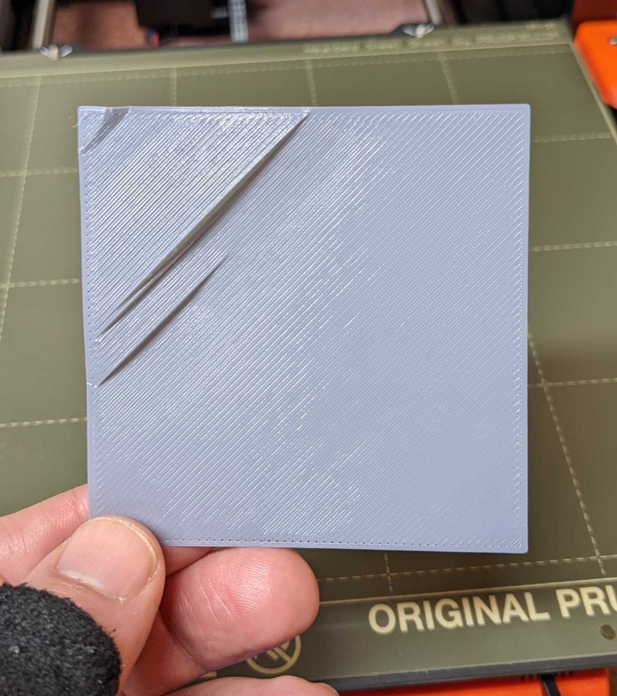
I printed the 75x75 calibration square and the result is repeatedly that the lower right is good, but the upper left much worse.
RE: Optimal Measurable Distance Between Nozzle and Bed?
Mesh bed leveling is an imperfect thing, it can't probe the entire bed so it takes samples and mathematically averages the spaces in between. Imagine it probes two points that are very close together but there is a dip between those points, that dip won't be averaged in and you'll get a poorer first layer in that dip. In the calibration wizard there's a reason why the little rectangle is close to the probe point. Increasing your probe points will improve your first layer, but even then you may have spots on the bed that aren't mathematically where the mesh leveling thinks it should be. This is complicated by fluctuations in the surface due to heat expansion.
Sometimes good enough is the best you can do.
Cheers
-Bob
Prusa I3 Mk2 kit upgraded to Mk2.5s, Ender3 with many mods, Prusa Mini kit with Bondtech heat break, Prusa I3 Mk3s+ kit
RE: Optimal Measurable Distance Between Nozzle and Bed?
How would I increase the probe points?
RE:
I have a mk2.5s so mines limited to a 3x3. I understand with the Mk3 you can increase it to 7x7.
https://help.prusa3d.com/en/article/mesh-bed-leveling_112163
Regards
-Bob
Prusa I3 Mk2 kit upgraded to Mk2.5s, Ender3 with many mods, Prusa Mini kit with Bondtech heat break, Prusa I3 Mk3s+ kit
RE:
I have to amend my last post. It turns out at some point the 7x7 was added to the MK2.5s firmware, so I can do that too. Slows down the bed probe but seems to work well.
Cheers
-Bob
Prusa I3 Mk2 kit upgraded to Mk2.5s, Ender3 with many mods, Prusa Mini kit with Bondtech heat break, Prusa I3 Mk3s+ kit
RE: Optimal Measurable Distance Between Nozzle and Bed?
Here's how it goes...
By rotating both Z-axis rods (printer must be off!), manually move print thead downward until tip of the nozzle just touches print sheet. In that position distance between print sheet surface and bottom of the SuperPINDA should be 1.5mm. If that's not the case, then manually adjust SuperPINDA height by lifting it up or down. Finally tighten the SuperPINDA.
After you do that, you must execute first layer calibration, where you adjust nozzle Z-offset properly. It's recommended that you start with default Z-offset value (which is zero) and then, during calibration (test pattern), you start to decrease Z-offset value. By doing that, you actually decrease distance between nozzle and print sheet, until the distance is "just right" (about 0.2mm). Obviously, you can't measure that distance during first layer calibration, because print head is moving -so you need to do it by eyesight. Just as a guide: if the distance between SuperPINDA and print sheet is about 1.5mm (as described previously), then you can expect usable first layer at Z-offset between about -0.600 and -0.800.I hope that was of some help for you.
Note that if you manually rotate the z-axis rods you will need to do a fresh z calibration since you have just screwed up its calibration (remember that the printer can't control the two sides individually)
Doing a z calibration now and then also doesn't hurt since one side can become slightly lower than the other over time.
This becomes more obvious if you have octoprint with the bed level visualizer plugin, then you can see if the whole bed appears tilted left or right, if it is, then do a z calibration and it should be more level.
And yes any adjustment to the pinda probe will completely mess up the z offset, might be easiest to just to a xyz calibration since, if i remember correctly, this one will reset all your saved sheets to zero and force you to thru new first layer calibration.