PINDA sensor placement
I assembled my kit without too much difficulty and then during calibration I kept getting the cryptic catch-all error "Calibration failed. Check the axes and run again." After pulling my hair out trying to find the problem I discovered that if the PINDA sensor was tightened in its holder it would stop working.
If I loosened the screw so that the PINDA was just sitting in the housing without being screwed in it would work just fine. I was able to complete calibration successfully. When I tightened the screw (even just a little) it immediately failed calibration until I loosened it again. Is the PINDA sensor going bad? I can't understand why it would stop working if the screw was even slightly tightened.
Re: PINDA sensor placement
I'm gonna go on a limb and assume you followed the instructions regarding pinda position at the "preflight" check instructions.
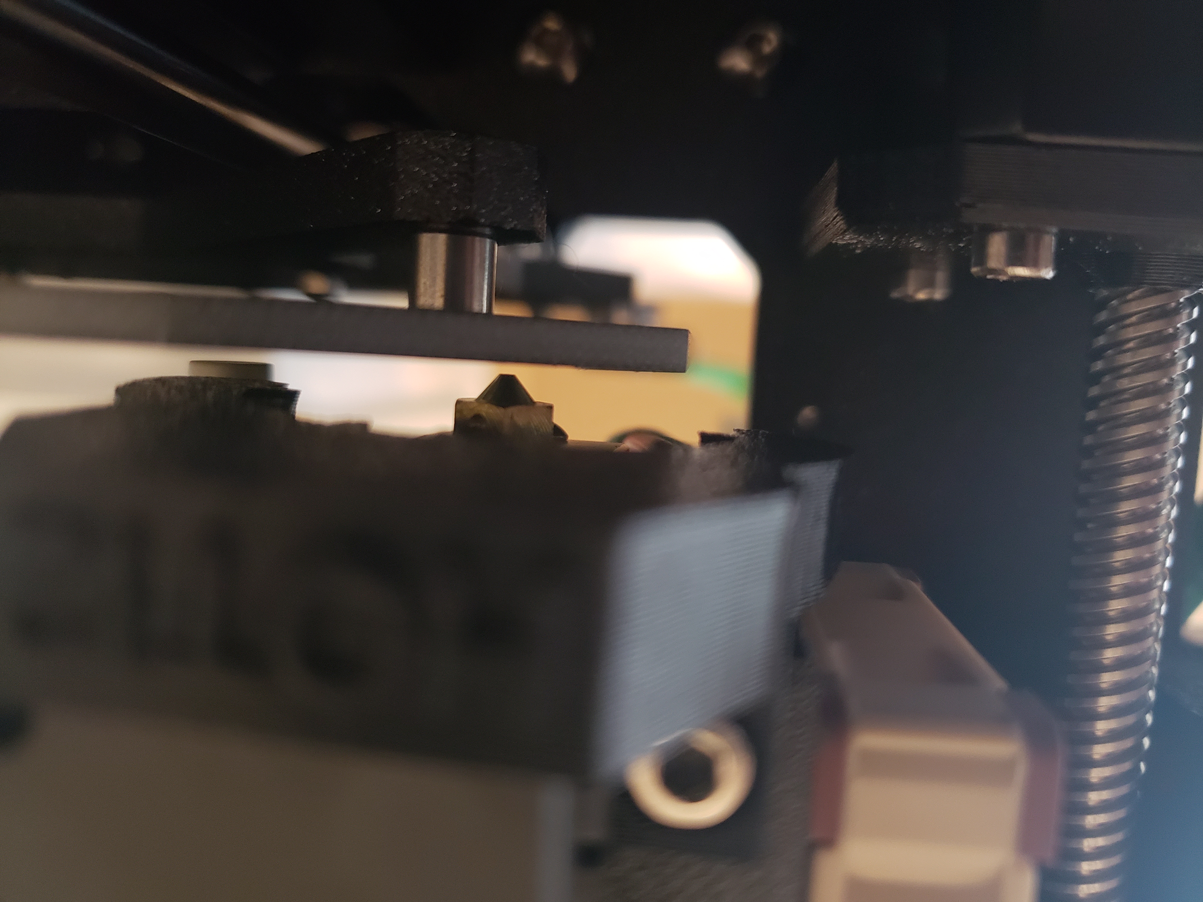
eg: Turn printer off, lower Z axis by turning the rods at the same time until nozzle touches heatbed. Place ziptie under Pinda and tighten.
Assuming that is, infact what you did, I would get on the "live chat" on the store page and request a replacement Pinda.
If assuming NOTHING is moving when you tighten it, there could in theory be something loose inside the Pinda. (which should be solid resin if it's anything like the proximity sensors I used to mess with in automotive machining)
Exactly what is it doing before it fails, and what is it doing exactly, when it stops.
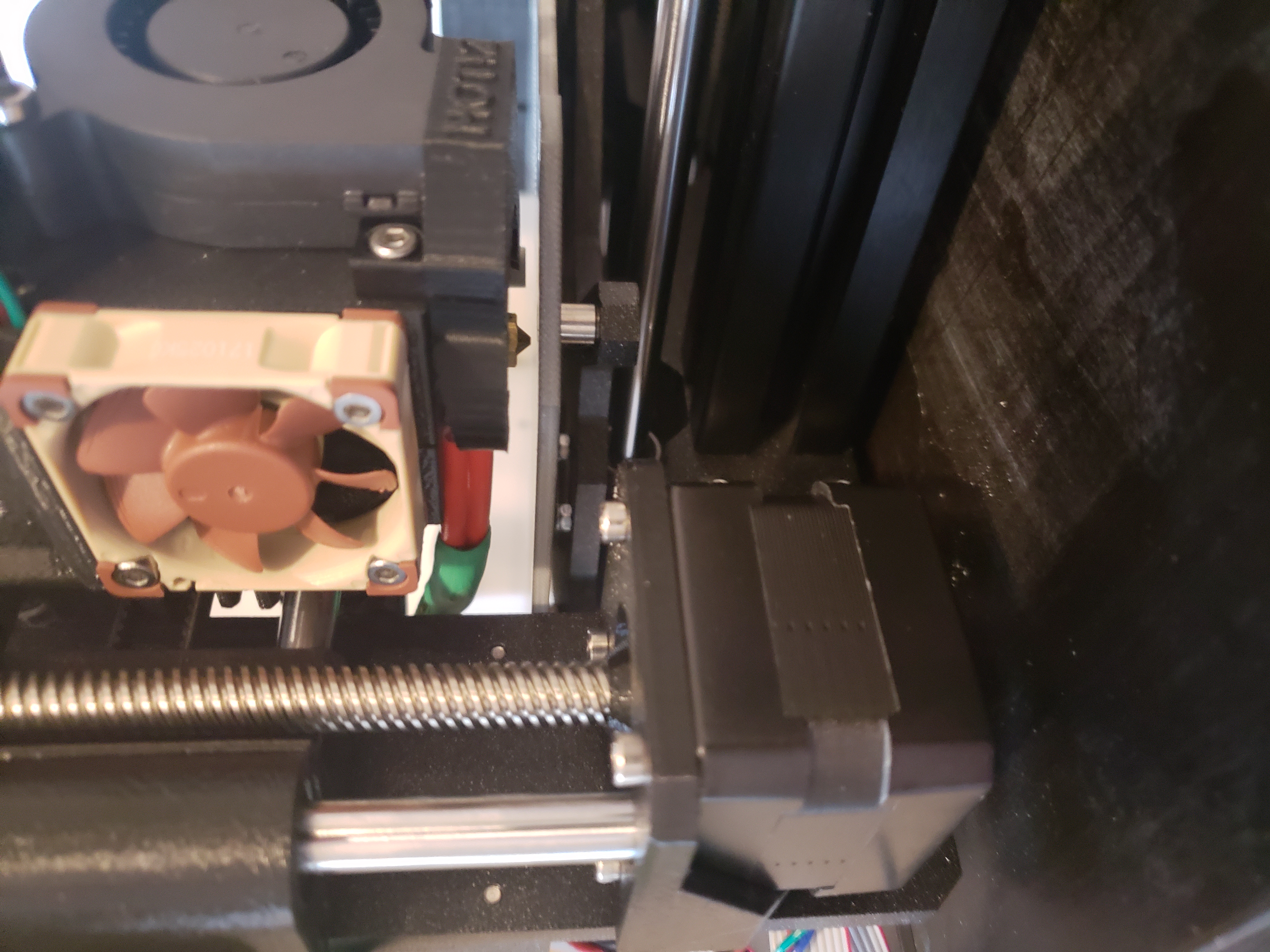
Pictures of the Pinda can help. (try to get it "level" with the nozzle, nozzle included in picture, so we can see height/angles/problems)
Hi, I'm Sean. I used to work on CNC machines.
I try to not make mistakes, but the decision is YOURS.
Please feel free to donate to my filament/maintance fund.
Re: PINDA sensor placement
The pictures attached aren't the best but the best I could do with my camera. The PINDA sensor is exactly one ziptie (middle of it) away from the bed when the nozzle touches the bed. I think you are right about the PINDA being bad. Although it passed calibration last night now I can't get it to pass. Half the time it gets to the XY point test and others it fails on the Z test, but even if it passes the Z test it fails on the XY test now
Re: PINDA sensor placement
Well chat support had me do the PINDA troubleshooting here: https://help.prusa3d.com/l/en/article/3tSXh6nWJd-pinda-probe-testing
Of course all the tests passed, but calibration still fails with "XYZ calibration failed. Please consult the manual." which the troubleshooting guide says means "Calibration point was not found at all". How could the calibration points not be found but the PINDA tests which finds the same spots pass without issue? When looking at the PINDA while it is doing it's tests I see the red LED blinking as it is passing over the metal points. I'm not sure why it is claiming that the calibration fails. Faulty motherboard or something?
Re: PINDA sensor placement
Well chat support had me do the PINDA troubleshooting here: https://help.prusa3d.com/l/en/article/3tSXh6nWJd-pinda-probe-testing
Of course all the tests past, but calibration still fails with "XYZ calibration failed. Please consult the manual." which the troubleshooting guide says means "Calibration point was not found at all". How could the calibration points not be found but the PINDA tests which finds the same spots pass without issue? When looking at the PINDA while it is doing it's tests I see the red LED blinking as it is passing over the metal points. I'm not sure why it is claiming that the calibration fails. Faulty motherboard or something?
What firmware version is on your printer?
I'm 99.9% sure your Einsy is fine.
Does the Y axis move "smooth" when doing the calibration points?
Does the X axis move "smooth" when doing the calibration points?
Does the extruder body, hit the X axis mounts on the sides? Or is something else hitting somewhere else? How about when the carraige goes all the way up Z to 210mm. Is anything hitting anything anywhere?
Are both of the X mounts parrallel on the Z rods?
I honestly have no idea, those are shots in the dark from me.
Hi, I'm Sean. I used to work on CNC machines.
I try to not make mistakes, but the decision is YOURS.
Please feel free to donate to my filament/maintance fund.
Re: PINDA sensor placement
Yup, all the movement is smooth and relatively quiet. I've watched all the movements to make sure that nothing is getting caught. Also, half the time I do a Z calibration it fails immediately asking if the steel sheet is attached (of course it isn't). I'll restart the test 10 seconds later and it finishes just fine.
The firmware is 3.1.3-245
Re: PINDA sensor placement
Does the XY calibration actually save any values or is it just to make sure your printer is built correctly? It passed with a "XYZ calibration ok. X/Y axes are perpendicular. Congratulations!" once before. I then stupidly cleared the results after tightening the PINDA screw to make sure the PINDA was working correctly. If it doesn't change the printing offsets or anything I'll just give up on trying to get it to calibrate as it is built correctly.
Re: PINDA sensor placement
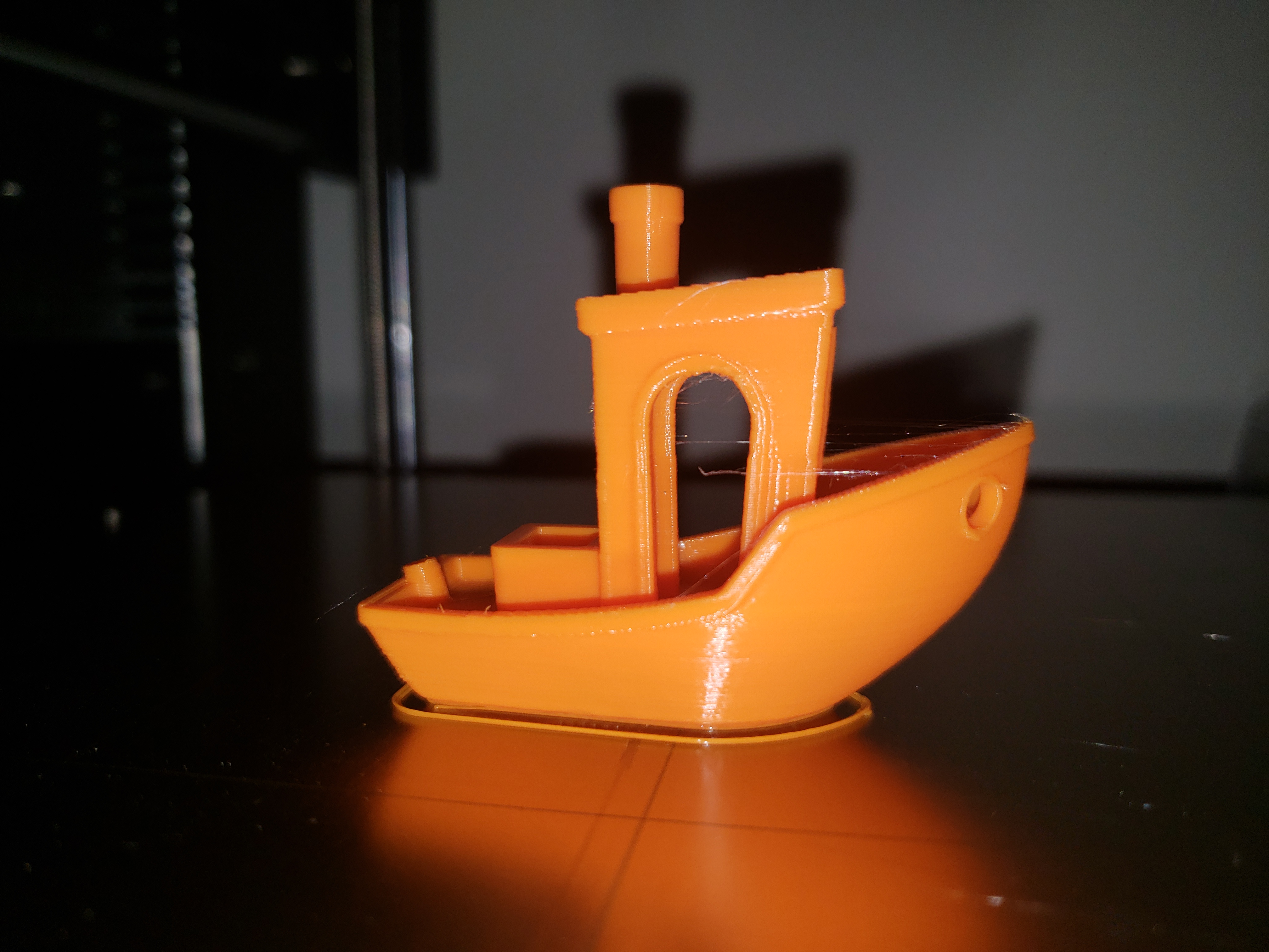
Turns out it was just a loose X belt. Even though it didn't feel loose the belt value was 290. I tightened it and was able to pass calibration. First print was a seemingly perfect benchy:
Re: PINDA sensor placement
The PINDA sensor is exactly one ziptie (middle of it) away from the bed when the nozzle touches the bed. ...
Could some possibly convert "One ziptie (middle of it)" into mm? (or microns, yards, furlongs, light years ...)
The PINDA height is pretty central to all this, and I don't know which ziptie we're talking about (got my Mk3 assembled) ...
-- Clint Goss
Re: PINDA sensor placement
The PINDA sensor is exactly one ziptie (middle of it) away from the bed when the nozzle touches the bed. ...
Could some possibly convert "One ziptie (middle of it)" into mm? (or microns, yards, furlongs, light years ...)
The PINDA height is pretty central to all this, and I don't know which ziptie we're talking about (got my Mk3 assembled) ...
I just measured a couple for you - 1.18 mm average from a dozen checks, 6 per tie.
Re: PINDA sensor placement
... convert "One ziptie (middle of it)" into mm ...
... 1.18 mm average from a dozen checks, 6 per tie.
Thanks!
So ... let's call the distance from the PINDA to the bottom tip of the nozzle along the Z axis the "PINDA Lift".
If the official PINDA Lift is one ziptie width above the nozzle (using the method of Chris3030 to place the nozzle on the bed and position the PINDA one ziptie width above the bed - not sure if that is the "official" method or not), then the recommended PINDA Lift is 1.18 mm.
My own assembled unit was shipped with PINDA Lift set to 0.82 mm. This seems much safer to me - especially if thicker print surfaces come into play (e.g. the BuildTak Print Surface, which by my calcs is 0.20 mm thicker than the PEI sheet on the Prusa Stock SSS). A thicker print surface would require an increased (i.e. less negative) Live Z adjust to move the nozzle further from the metal steel sheet. At some point, the PINDA will move out of sensitivity range.
Also, the thickness of the steel sheet may come into play - the BuildTak FlexPlate is significantly thinner than the Prusa SSS - possibly causing PINDA sensing issues because the there is less "metal meat" to sense.
I have seen recommendations for PINDA Lift as low as 0.30 mm (can't recall where). However, this increases the risk that warped / curled / lifted parts can be whacked by the PINDA (or vice-versa).
-- Clint Goss
Re: PINDA sensor placement
If the official PINDA Lift is one ziptie width above the nozzle (using the method of Chris3030 to place the nozzle on the bed and position the PINDA one ziptie width above the bed - not sure if that is the "official" method or not), then the recommended PINDA Lift is 1.18 mm.
Go look here https://manual.prusa3d.com/Guide/9.+Preflight+check/514?lang=en in the manual for the Prusa instructions on PINDA setting (that presumably you may not have seen as you bought an assembled printer) for "official".
Re: PINDA sensor placement
Thanks again John!
The comments for Chapter 9, Step 3 are telling. They confirm your measurement of the PINDA Lift Calibration Device (the ziptie) and also catalog a number of sentiments on needing to be lower than 1.2ish mm.
-- Clint Goss