Seeking Clearance & Printing Suggestions
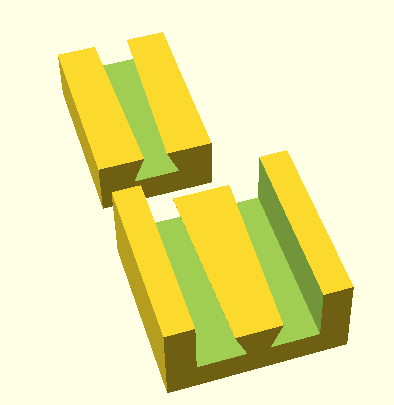
The two parts in the photo are 15 mm square. They will each be attached to separate pieces (not shown) and they will mate and slide together. You can see how the male piece on the left will slide into the female on the right. I plan to print these in Prusa PETG once I receive my recently ordered printer.
My questions have to do with clearances between the two parts and print settings. I want a snug fit that requires a little force to fit the pieces together and that will hold them together until they are pulled apart, again, with a little bit of force. Something of a press fit, with a little interference if I'm using the terms correctly. The parts may go through several mating cycles per week so it can't be a struggle to attach and separate them, but they can't too easily slip apart from each other. I realize that ambient temperatures an other factors will influence how well the parts mate and they may be great at one temperature and not so good at another, but I have to start somewhere.
The parts also need a little bit of strength. They won't be holding much weight, less than a pound I expect, but I don't want them to break while they are being engaged or disengaged because of the forces applied to them during that process. Since the surfaces need to be somewhat smooth to aid in the mating process I rather expect one of the finer settings. Would the .05mm setting be the way to go or might another less demanding setting suffice? Would setting the clearances between the two piece at .1mm b3e a good starting point? More? Less?
Thanks.
![]()
It depends how they are going to meet: If from the position in the picture and slide together and if they are also printed in that orientation them 0.5 will probably do.
But if a straight face-to-face push across the lay of the filament then 0.1 or more might be needed.
And if the slide fit would permit counter shaped wedges then tolerance would be less important.
Cheerio,
RE:
It depends how they are going to meet: If from the position in the picture and slide together and if they are also printed in that orientation them 0.5 will probably do.
But if a straight face-to-face push across the lay of the filament then 0.1 or more might be needed.
And if the slide fit would permit counter shaped wedges then tolerance would be less important.
Cheerio,
Thanks for that.
The pieces will slide. They will be attached to other pieces. I am as yet uncertain as to their orientation during printing. I expect it might be necessary to orient the female pIece so as to avoid the necessity for support material as I don't think I would be able to adequately clean out the cavity: 90° rotation so the cavity points up.
I understand print orientation effects the prints but as a newbie the details of exactly how are not yet well understood.
Are you thinking they should be printed at the .05 mm quality setting? That would mean very long print times because these pieces are but small components of much larger objects. I might be able to get away with gluing then on, however, so I could conceivably print the larger parts at a lower resolution to save time.
When you suggested wedges were you thinking of the central channel and rail? I can see how that might make mating easier but my concern would be it might allow more movement when the parts are mated.
RE: Seeking Clearance & Printing Suggestions
Are you thinking they should be printed at the .05 mm quality setting?
0.2 should be fine.
Could you make it progressive so they jammed - something lke this?
Cheerio,
RE: Seeking Clearance & Printing Suggestions
What you're showing me looks something like a dovetail joint but with the central element of the female part in the foreground inverted. I'm not sure if that was your intention and if it was just how exactly that's supposed to work.
It's effectively a tapered keyway. The stl is untested but should print in a couple of hours if you want to test the concept. I used 0.1mm tolerance.
Cheerio,
RE: Seeking Clearance & Printing Suggestions
Thanks.
I see now, when one of the parts you made is inverted, as it would be in use, the central channel and rail of the two pieces have the same profile. I didn't realize that at he time of my previous post so I couldn't see how they would fit together. Duh! Your idea is worth trying out and I may do so when my printer arrives. I think the dovetail or wedge design, whatever one calls it, may offer some additional stability over just a square or vertical profile for the center channel and rail. A bit of a fillet or chamfer on the mating edges might help them align during the mating process.
I like to move things around in the 3D view of my CAD software (FreeCAD) to see how things line up and fit. I can't do that with the STL file you provided but I should be able to model something similar easily enough.
Thanks again.