Wrong vertical dimensions because of bridging
Dear Experts,
I had already issues with several parts where exact dimensions are required. I didn't figure out yet how to get a correct height if bridges are required.
In the graphic below I'm trying to explain what my issue is -> if my STL model has an overhang which should be exactly 1 mm from the bed base, (here with 0.2 mm layer height) PrusaSlicer creates a bridge infill at upper level 1,2mm (same as the model's layer); but - as the bridge's height is more than 0.2 mm, the remaining space below is only ca 0.8 mm.
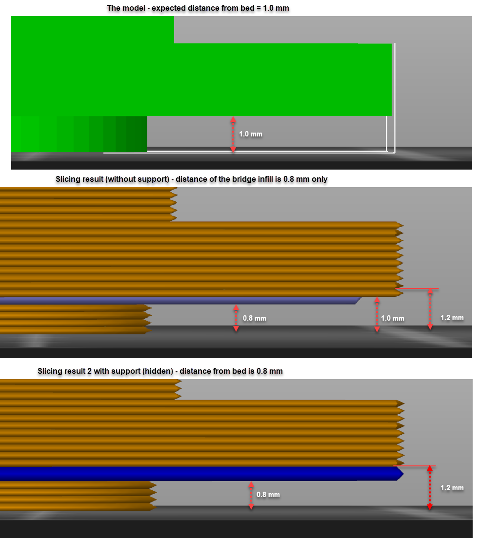
What would be the correct way to get the correct distance? I assume the bridge should be created 0,2mm higher; but I didn't find a way to influence it. (well - I could change the STL, but I think that is not really the way to go -> I'm creating my models in Fusion360 and it does make sense to have correct measures there..)
Btw. (different but related topic) I am also wondering which tweaks are there to ensure a correct horizontal dimensions -> In a recent project, I created one object with an ISO M16 female thread and another object with an M16 male thread -> the printed objects didn't fit together as both objects were printed with ca. 0,1 mm additional material horizontally. I solved this by changing the STL model, but are there any hidden options in PrusaSlicer to influence that that e.g. the border extrusion is not exact on the model's outer face but e.g. 0,1 mm back (similar to that "elephant foot compensation", but for the whole model..)?
Thanks in advance for your qualified answers,
Karl
RE: Wrong vertical dimensions because of bridging
Printing threads:
Threads are difficult to print as the "overhang" sags down and the edge is not sharp.
I usually retract the thread face 0.1 - 0.2mm on both male and female part to get a fit (model). This gives perfect working threads with not too much friction.
Have a look at my models on Printables.com 😉
RE: Wrong vertical dimensions because of bridging
@area51
OK changing the CNC model is what I planned to avoid .. (that's exactly what I did last time - it's just a bit complicated in Fusion360 - where just creating an ISO sized thread is a 10sec task..).
However I learned in the meantime there are some filamant settings I didn't realize/understand yet like XY compensation, changing the outer perimeter width or print outer border first ... I think I will play around with that.
However the topic with the bridge is annoying me more at the moment...
Thanks for your comments!
RE: Wrong vertical dimensions because of bridging
Would you mind posting a (zipped up) version of your saved project .3mf if you can so we can experiment with the settings and look at the model etc.
RE: Wrong vertical dimensions because of bridging
@karlpe
I understand and agree that it is an extra step (should not be necessary...). Did the modifications in F360 too by pushing the the inner curved plane 0.1 mm.
I would like to see a better solution too, still respecting the other dimensions of the model.
Have a look at my models on Printables.com 😉
RE: Wrong vertical dimensions because of bridging
@neophyl
Sure, I appreciate any support 🙂 .
I hope the upload works that way:
RE: Wrong vertical dimensions because of bridging
To me that definitely looks like a slicer bug. I even double checked the model dimensions in a 3rd party tool just to make sure it wasnt like 0.99999 or something weird like that for that height.
I'd post it over on github with your 3mf file for the devs to take a look at.
Out of curiosity what happens if you make that dimension 1.0001 or similar on the model and try and slice it ?
RE: Wrong vertical dimensions because of bridging
@neophyl
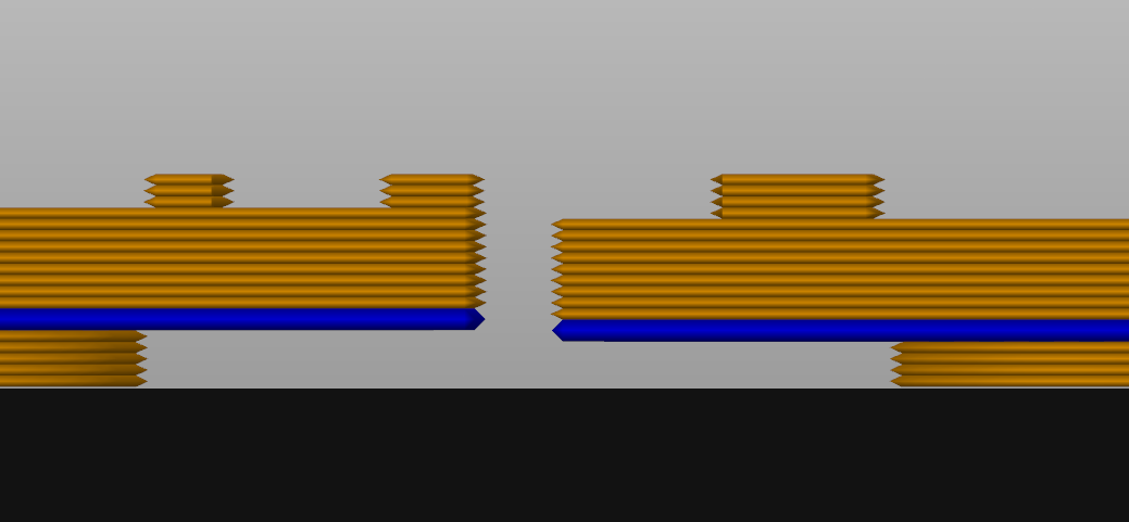
left side is with 1,10 mm; Right side with 1,09 -> so it seems it always selects the closest 0,2mm layer level.
RE: Wrong vertical dimensions because of bridging
well, the longer I am thinking about that, the more I think I feel that is not really a bug, but a non-feature...
I assume, the slicer simply calculates the height dimension in the fixed 0.2mm layer height. It realizes at some time that there is a bridge and changes eventually the filament flow, but it still follows the path in the given 0.2 layer height.
To eliminate that dimension gap completely, the slicer should know that the thickness of the bridge will be close to 0.4 mm, so it should skip it in the current layer and print it in the next higher layer (or even two layers higher if the layer height is smaller).
That sounds like complex logic for me, even if it would make PS more perfect. But then, you have to think about much more optimization potential - e.g. automatic dynamic layer height adjustments, to achieve accuracy of 0.1, 0,05 mm even if the layer height is 0.2 etc.
I am quite sure such options will be there somewhere in future (e.g. CAM systems for milling have such possibilities already), but looking at PS's GitHub page I see there are many many other topics to solve...
RE: Wrong vertical dimensions because of bridging
Thanks for checking out what it does karlpe, I shall have to take that into account if I’m designing anything will size critical bridges.
RE: Wrong vertical dimensions because of bridging
Hi guys,
I'm currently design parts for slot cars where every tenth of mm counts. After a quick check on PS Github, I found the following "interesting" issues :
https://github.com/prusa3d/PrusaSlicer/issues/3783
https://github.com/prusa3d/PrusaSlicer/issues/3458
RE: Wrong vertical dimensions because of bridging
Although Team Prusa has done some amazing work since forking away from the original Slic3r code base, there are still some areas where PrusaSlicer has competition. In researching this, my understanding is that there were sound historical reasons behind the approach used by PS/Slic3r but technology developments have made those less of a problem. We're basically stuck with a layer of stringy support under every supported surface. Other slicers are under heavy development as well, and if you require a lot of removable support, I suggest checking out ideaMaker from Rasie3D (also free but not open-source).
Here's a comparison 2mm thick test piece printed with the 4 slicers I encounter most often, left-to-right, top-to-bottom ideaMaker, Simplify 3D, PrusaSlicer 2.2, and Cura:

Long-term, adding comments and documentation to the open GitHub issues is the best strategy for getting these issues bubbled higher up in the developer priority list. For today, if I need removable supports that look reasonably good, I use ideaMaker. Note though that there is still a ~0.2mm deviation with any of the alternate slicers. If you still want to use PrusaSlicer, try using variable layer heights for a bit more accuracy.
If you truly need 0.1mm precision, look into re-orienting your part to eliminate or reduce support on critical layers, or break it into sub-assemblies that can be printed without support and assembled later.