Strange gap between infill and shell
Hello,
I hope they can help me here.
Unfortunately I cannot explain the following gaps between the shell and the infill.


I've tried everything.
- different types of filament (PLA / PETG)
- rotated component by 90°
- changed the position of the component to a completely other point on printbed
- (de)activated Z-Lift
- (de)activated wipe
- Cooling 0%, 50%, 100%
- Infill/Perimeters overlap: 25%, 50%
- EM: 0.8 - 1.0
- Extra Perimeters if needed on/off
- Detect Thin Walls on/off
- changed nozzle-temperatur +/- 10°C
- Retract 1.5mm / 1.0mm / 0.5mm / 0mm
I can eliminate Hardware-issues ... bevause it works with Cura.
Somehow, I think Prusaslicer's trying to pull my leg.
https://www.3d-druck-community.de/showthread.php?tid=27851
"Test"würfel" mit Loch" - 3DDC_paradroid_Testcube_V2.stl
(To speed it up, the lower 50-70% can simply be cut away in the slicer)
I have also tried various versions of Prusaslicer - including the current 2.2.0 RC4.
Nothing ever changes in this gap, it just stays there all the time, unless I turn the EM so high that the whole pressure becomes extremely bad.
Anybody got any more ideas?
Best Answer by Neophyl:
I ran a series of prints with both the stock prusa profile and variations on yours.
I dont have an X1 and I only had PLA handy so theres a considerable difference to start with right there.
Left to right (1-5)
1 is a default prusa 0.2 layer height speed print settings profile, my usual PLA and my usual printer profile (its a modified MK3 with a butterworth & bunny geared extruder)
2 is your Print settings but my PLA and my printer profile
3 is as 2 but I changed the default extrusion width to 0 to leave them all on automatic instead of the 0.4 you had (was curious what difference this would make).
4 your Print settings but my PLA settings with reduced Extrusion Multiplier to 0.84 and my Printer Profile
5, same as 4 but with firmware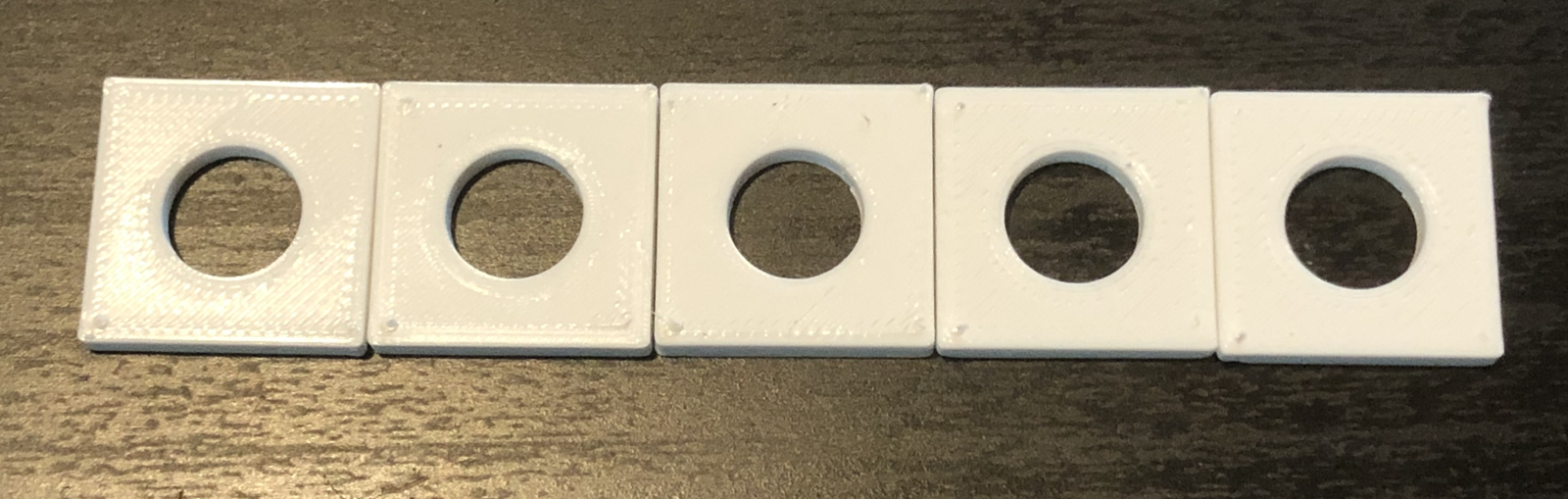 flavour set to Reprap/Sprinter instead of Marlin
Its very hard to make out due to the filament (and no so great camera work on my part) so heres a contrast enhanced version
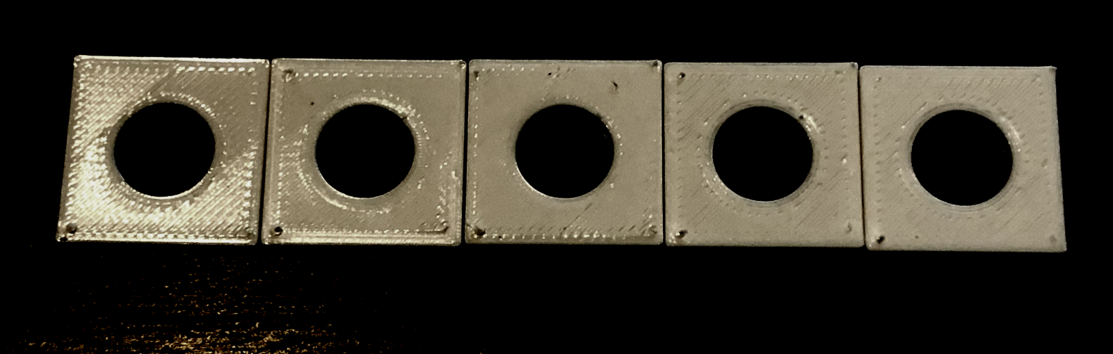
I Number 1 is over extruded, its a default prusa profile and the filament was left at 1.75 so I'm unsurprised. No real gaps in the top surface though and a slight bump where the changed direction of top infill meets.
Number 2 was actually the best of the top surfaces, that is your settings for Print profile but with the filament left at 1 EM and 1.75.
Number 3 was very close to 2 but under magnification and feel its ever so slightly rougher than 2. Probably down to the default extrusions now being 0.45 as it was all on default.
Number 4 with the reduced 0.84 EM is where there's gaps between the lines starting to show up in general.
Number 5 is identical to 4 so the difference in gcode flavour didnt make any difference to me. Then again the settings in Machine limits will match those is the MK3 firmware so thats not surprising either. You should always make sure the settings in the slicer match your firmware, just for the sake of getting the print time estimates to be more accurate if nothing else. As Bob points out if they match then theres not going to be an issue with Slicer sending them in the gcode either.
I will also mention that both 4 and 5 are under sized coming in at around 19.88mm instead of 20mm due to the lowered extrusion multiplier.
With a properly calibrated steps per mm it really shouldn't be that far out. I always use this guide https://mattshub.com/blog/2017/04/19/extruder-calibration to get it set and saved and its extremely accurate afterwards.
One other thing I noticed about your Printer Settings is that its set to use absolute extrusion positioning (Relative extrusion unticked) which is different than the norm for Marlin used on both the Mk3 or the CR10.
May be Bob can draw some conclusions but as I cant seem to duplicate the issue then I'm afraid I cant think of anything else to add at this time. I'd try the same print with some PLA just to see if it does the same as your PETG. I'd also try different top infill patterns, something like concentric. Finally one other thing I'd try is to load the project into Slicer++ which is forked from Prusa Slicer and give that a go. Sometimes it does produce different results so its worth a go. https://github.com/supermerill/Slic3r/releases
RE: Strange gap between infill and shell
Unfortunately you have to be a member of that community to download the file. I am not joining another forum just to check out a random stl file 🙂
If you wouldn't mind saving your project as a 3mf (File>save projects as) and zipping it up and attaching it here we can then look at all your settings as well as the model itself. Someone might then be able to figure it out.
RE: Strange gap between infill and shell
Oh sorry and thx for clearing up.
Here's my project
(Extruder-steps are calibrated and everything is fine, even size accuracy of components - only this gap are annoying
Don't Mind that EM is set to 0.84 - that fits with this M4P-PETG very good in other prints)
RE: Strange gap between infill and shell
Cheers. I'll give it a go when I get home. Got a few questions though if thats ok ?
Is your printer actually an Artillery X1 ? If so have you changed the firmware as I notice the Gcode flavour is set to RepRap/Sprinter and I thought the X1 used Marlin ?
That extrusion multiplier is set very low, a lot lower than I would expect but as you say its calibrated I guess it cant be that.
Is there any reason you are over riding the extrusion widths defaults on most of your perimeters ? By setting it to 0.4 it is also using 0.4 for the other perimeters rather than 0.4*1.125=0.45mm which is what they would be if you left the default extrusion width at 0 too.
Edit - sliced it at work and Ive just noticed something weird, the perimeters are set to 2 and there are 2 on the bottom and on the infill layers but the top 2 layers have 4 perimeters for some reason. I havent spotted any modifiers or anything so wonder why the top 2 layers have twice the perimeters ?
RE: Strange gap between infill and shell
@neophyl
Is your printer actually an Artillery X1 ? If so have you changed the firmware as I notice the Gcode flavour is set to RepRap/Sprinter and I thought the X1 used Marlin ?
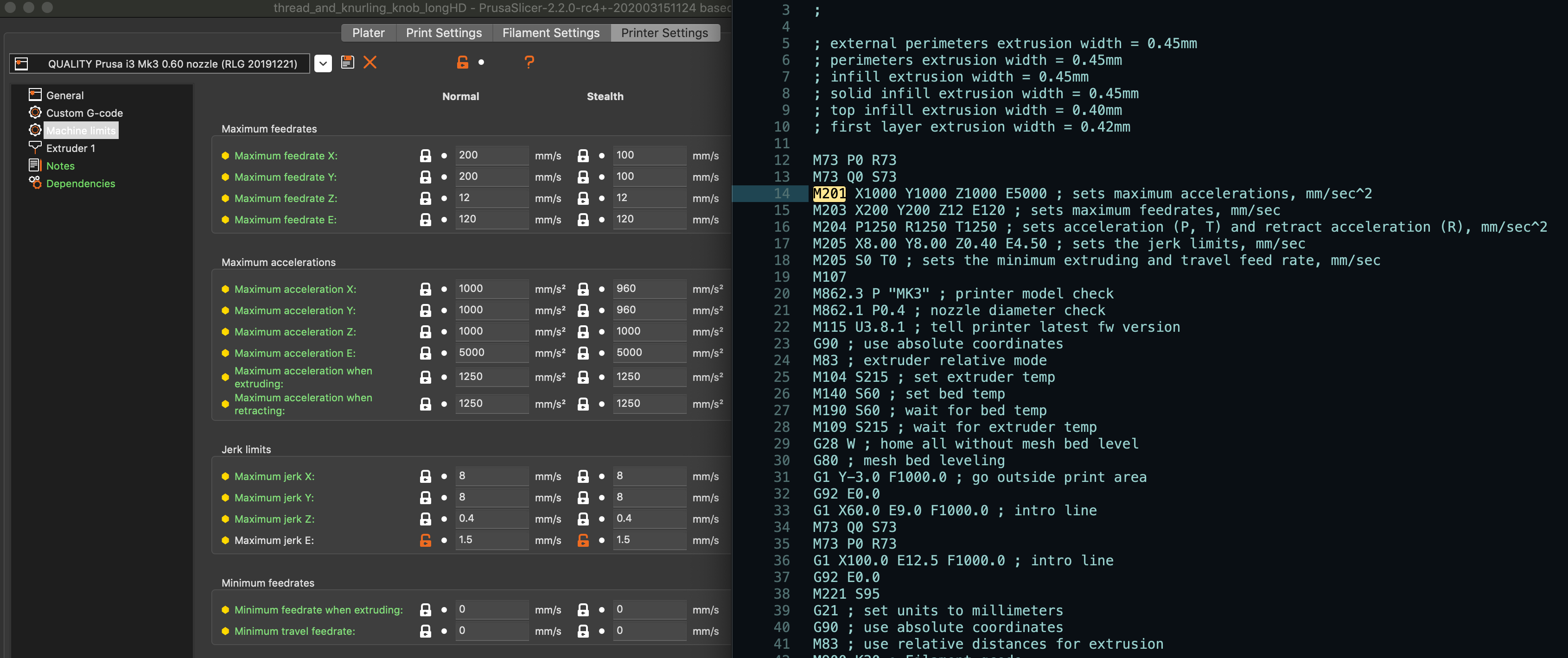
Yes, it is a Sidewinder X1 with Marlin....BUT when you use "Marlin" in Prusaslicer, PS will take some M-codes before the complete gcode (M201 - M205) which will override some acceleration settings of the firmware.
Prusaslicer can only arrange ONE Acceleration for Print and Travel - so one of these acc's @ Marlin-Firmware will be wrongly overritten by Prusaslicer.
Somewhere there was a github issue on this topic
The only difference by using "gcode Type RepRap" is that RepRap won't include those M-codes to gcode....the code is the same.
That extrusion multiplier is set very low
It's really hard to see, but here's a picture:

On the Left:
FD: 1.75
EM: 1.0
Middle:
FD: 1.72 (messured)
EM: 1.0
Right:
FD: 1.72
EM: 0.9
Left and Middle are much over-flowed.
I know it's weird, but the extruder is calibrated and the parts fit very well with these settings. The whole part itself looks good too - it's just that one gap that remains.
Is there any reason you are over riding the extrusion widths defaults on most of your perimeters ?
Yes, that was intentional...I think 0.45mm is very wide...partly I printed with 0.36mm for a finer result - but unfortunately the setting does not change the gap.
the perimeters are set to 2 and there are 2 on the bottom and on the infill layers but the top 2 layers have 4 perimeters for some reason.
Haha for the reason I have also searched longer. That's because of the setting "Extra perimeters if needed".
If you disable this, on the Top would be only two perimeters, also.
RE: Strange gap between infill and shell
[...] Yes, it is a Sidewinder X1 with Marlin....BUT when you use "Marlin" in Prusaslicer, PS will take some M-codes before the complete gcode (M201 - M205) which will override some acceleration settings of the firmware. Prusaslicer can only arrange ONE Acceleration for Print and Travel - so one of these acc's @ Marlin-Firmware will be wrongly overritten by Prusaslicer.
Not sure if I'm understanding you completely, but if I set the correct parameters in the PrusaSlicer Print Settings->Machine Limits tab, the generated gcode M20x commands match.
RE: Strange gap between infill and shell
I ran a series of prints with both the stock prusa profile and variations on yours.
I dont have an X1 and I only had PLA handy so theres a considerable difference to start with right there.
Left to right (1-5)
1 is a default prusa 0.2 layer height speed print settings profile, my usual PLA and my usual printer profile (its a modified MK3 with a butterworth & bunny geared extruder)
2 is your Print settings but my PLA and my printer profile
3 is as 2 but I changed the default extrusion width to 0 to leave them all on automatic instead of the 0.4 you had (was curious what difference this would make).
4 your Print settings but my PLA settings with reduced Extrusion Multiplier to 0.84 and my Printer Profile
5, same as 4 but with firmware flavour set to Reprap/Sprinter instead of Marlin
Its very hard to make out due to the filament (and no so great camera work on my part) so heres a contrast enhanced version
I Number 1 is over extruded, its a default prusa profile and the filament was left at 1.75 so I'm unsurprised. No real gaps in the top surface though and a slight bump where the changed direction of top infill meets.
Number 2 was actually the best of the top surfaces, that is your settings for Print profile but with the filament left at 1 EM and 1.75.
Number 3 was very close to 2 but under magnification and feel its ever so slightly rougher than 2. Probably down to the default extrusions now being 0.45 as it was all on default.
Number 4 with the reduced 0.84 EM is where there's gaps between the lines starting to show up in general.
Number 5 is identical to 4 so the difference in gcode flavour didnt make any difference to me. Then again the settings in Machine limits will match those is the MK3 firmware so thats not surprising either. You should always make sure the settings in the slicer match your firmware, just for the sake of getting the print time estimates to be more accurate if nothing else. As Bob points out if they match then theres not going to be an issue with Slicer sending them in the gcode either.
I will also mention that both 4 and 5 are under sized coming in at around 19.88mm instead of 20mm due to the lowered extrusion multiplier.
With a properly calibrated steps per mm it really shouldn't be that far out. I always use this guide https://mattshub.com/blog/2017/04/19/extruder-calibration to get it set and saved and its extremely accurate afterwards.
One other thing I noticed about your Printer Settings is that its set to use absolute extrusion positioning (Relative extrusion unticked) which is different than the norm for Marlin used on both the Mk3 or the CR10.
May be Bob can draw some conclusions but as I cant seem to duplicate the issue then I'm afraid I cant think of anything else to add at this time. I'd try the same print with some PLA just to see if it does the same as your PETG. I'd also try different top infill patterns, something like concentric. Finally one other thing I'd try is to load the project into Slicer++ which is forked from Prusa Slicer and give that a go. Sometimes it does produce different results so its worth a go. https://github.com/supermerill/Slic3r/releases
RE: Strange gap between infill and shell
but if I set the correct parameters in the PrusaSlicer Print Settings->Machine Limits tab, the generated gcode M20x commands match.

You cannot differe between Print-Acc and Travel-Acc in Prusaslicer - in Marlin you can!
E.G. in my Marlin-Printer-Firmware these Values are set:
Recv: echo:; Acceleration (units/s2): P<print_accel> R<retract_accel> T<travel_accel>
Recv: echo: M204 P800.00 R10000.00 T2000.00
P800, T2000 -> With Prusaslicer you would override one of these two Values to the other.
The Green marked section in Gcode is the only difference between Marlin- and Rep-Rap-pre-selection flavor in Prusaslicer
I've compared different difficult Objects and sliced them once with marlin- and once with reprap-flavor....it is exact the same gcode biside the M-codes above.

Here is an Github-Issue to that: https://github.com/prusa3d/PrusaSlicer/issues/2755#issuecomment-520789998
Of course...the time-calculation in Prusaslicer differs between these two settings....but it's not that much and only one protection anyway.
@Neophyl
Wow, thanks for your time!!!
One other thing I noticed about your Printer Settings is that its set to use absolute extrusion positioning (Relative extrusion unticked) which is different than the norm for Marlin used on both the Mk3 or the CR10.
I honestly never thought about it. I'll look into it again.
I've done a lot of testing

And I was sure the E-Stepsettings are right.
When I extrude 10*10mm, there went exact 100mm Filament into the extruder.
But I'll give it a chance and I will check that tomorrow again.
Also I would try Slic3r.
I can't explain it to myself, with me I can reproduce the problem again and again - no matter how, no matter in which position ... but ONLY with Prusaslicer.
When I use Cura for slicing, everything is ok...so some Cura setting has to straighten something that I seem to have screwed up somewhere.
If only Cura wasn't so cruel to use.
I'll keep at it, thank you very much for your efforts!
RE: Strange gap between infill and shell
So, there's news.
For the sake of completeness, I would like to mention this.
It seems that my extruder gear slipped during faster accelerations.
I have now installed a new (other) extruder gear and a new nozzle and the problem is gone.
Why the problem did not occur with Cura I can only deduce that PS on this corner probably accelerated faster than Cura.
Thanks again for the help 🙂
RE: Strange gap between infill and shell
Thanks for letting us know. Often people don't when they have something fixed and anyone coming along later reading the thread as they have a similar issue is left in the dark so much appreciated.
RE: Strange gap between infill and shell
Hi @foodfighter
What do FD and EM stand for? Where can I change those values?
RE: Strange gap between infill and shell
Fd was a shorthand for filament diameter. That is set in your filament profile.
em was short for Extrusion Multiplier which is also set in filament settings.
RE: Strange gap between infill and shell
@neophyl
Is it bad idea to set EM over 1?
RE: Strange gap between infill and shell
Setting your extrusion multiplier higher is basically telling Slicer to extrude more filament. That's for all types of extrusion. Its normally done if your printer is under extruding. This can be down to certain filaments which is why its a per filament setting.
However if your filament diameter is set to match the actual average of what the filament is and if your extruders steps per mm are correct there really shouldn't be any need to set an Extrusion Multiplier other than 1.