Slicer Settings for Screw Head Counterbores
Need some advice for printing counterbores, used to keep screw heads flush with or below the printed surface, aka "countersinking".
The slicer orientation for these holes is flat to the build plate which avoids printing excessive amounts of support for other areas of the part.
I've tried printing these counterbores without supports, but the bridging results are not particularly good, leaving a droopy surface. Printing with supports is better, but not that much better and creates another post-processing task.
I can workaround the issue by creating a thin, sacrificial surface across the screw hole. This causes PrusaSlicer to make straight bridge lines across the circular void. BUT, this is a time consuming task that I have to do in modeling. Would really like to avoid that if possible.
Is there a setting I can adjust in PrusaSlicer that will allow for straight bridging across these types of circular structures?
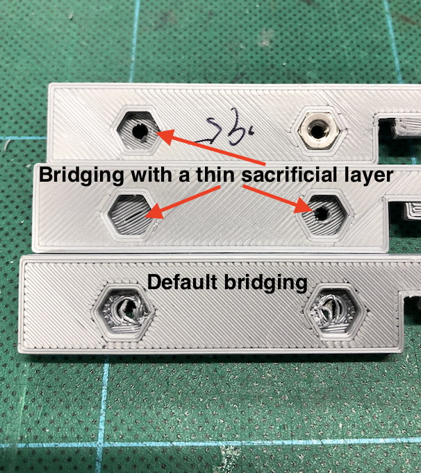
If I haven't explained this clearly enough, perhaps the photo below can do a better job. The two printed parts at the top used the sacrificial layer technique. I just punch through the strands with a screw. The bottom printed part shows the bridging result when models with counterbores are sliced without supports.
Thanks!
RE: Slicer Settings for Screw Head Counterbores
Simple answer - Not in Prusa Slicer no.
That function is available in Super Slicer though. https://github.com/supermerill/SuperSlicer/releases/tag/2.2.53.4 (that's the stable version, don't download the 2.3.55 versions as they are based on the Prusa Slicer Alphas and so have all the issues the alphas had).
Super Slicer is a fork of Prusa Slicer. Its laid out a bit differently but it will be familiar if you are familiar with PS. It has loads more 'experimental' options. Including many of the asked for ones not in PS (yet). Basically its like a tinkerers toolbox of PS.
btw if you use the correct support settings in PS the supports will just pop out if you push against them through the hole. Takes seconds. If you are using the support defaults you will find them difficult to remove.
The settings you need are under Perimeters & Shell > Advanced. There's several options relating to perimeters on bridged areas. One of them automatically just bridges the entire hole.
Generally though its better to build them into your model, that way any slicer including PS will do it.
RE: Slicer Settings for Screw Head Counterbores
Hi Rocheros
If you model your Nut recesses, like this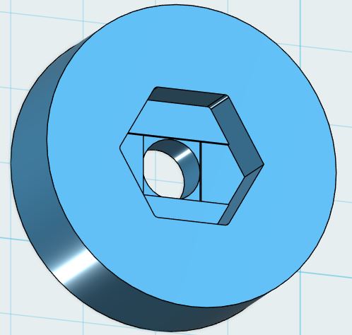
Your Nut Pocket should slice like this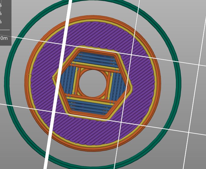
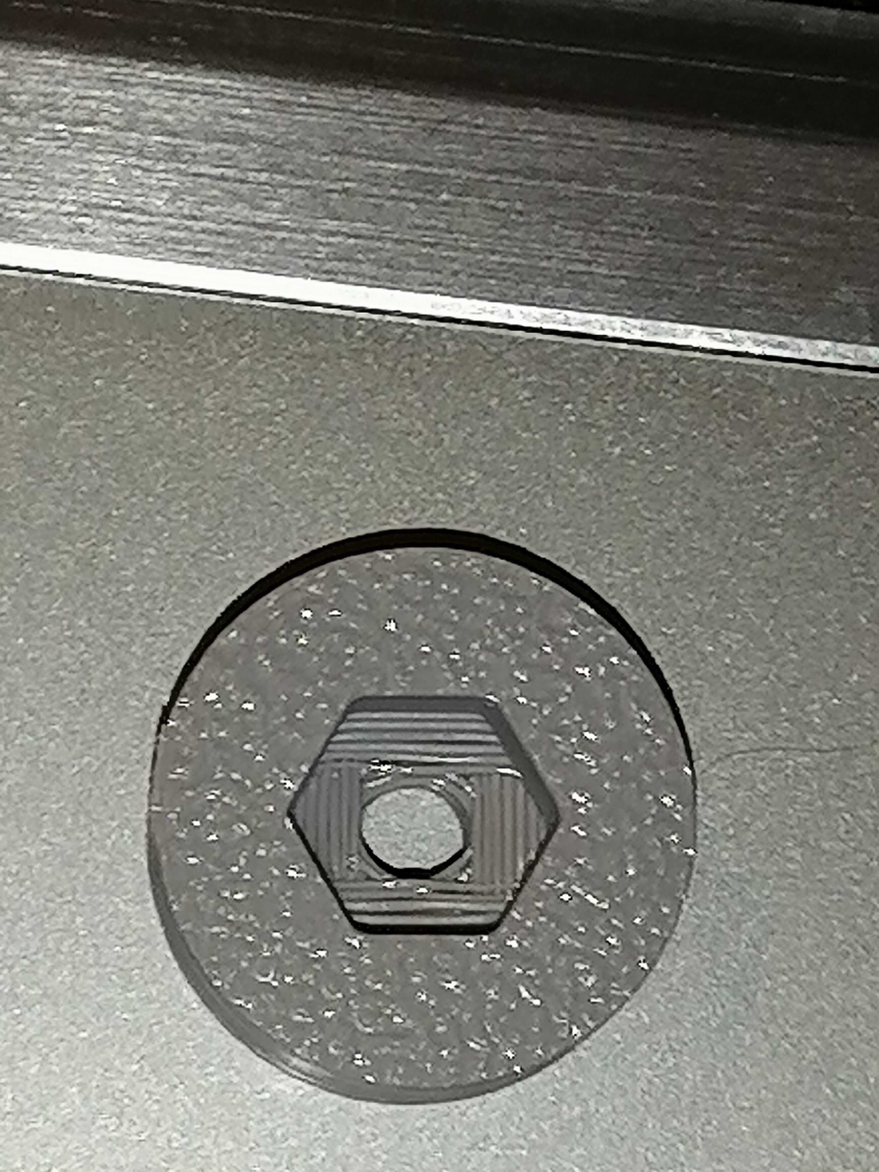
and the finished printed result should look a bit like this
Regards Joan
I try to make safe suggestions,You should understand the context and ensure you are happy that they are safe before attempting to apply my suggestions, what you do, is YOUR responsibility.Location Halifax UK
RE: Slicer Settings for Screw Head Counterbores
Thanks, Neophyl and Joan for the expert advice!
Some lovely workarounds/solutions you've given me.
Greatly appreciated!
--Steve
RE: Slicer Settings for Screw Head Counterbores
Oh Joan, what a great solution.
RE: Slicer Settings for Screw Head Counterbores
@towlerg
Thank you,
It was something passed on to me, by Murathan at Zaribo.
regards Joan
I try to make safe suggestions,You should understand the context and ensure you are happy that they are safe before attempting to apply my suggestions, what you do, is YOUR responsibility.Location Halifax UK
RE: Slicer Settings for Screw Head Counterbores
@JoanTabb this goes into more detail about what you were talking about: https://hackaday.com/2020/05/17/look-ma-no-support-for-my-floating-holes/
RE: Slicer Settings for Screw Head Counterbores
Thanks Sam
regards Joan
I try to make safe suggestions,You should understand the context and ensure you are happy that they are safe before attempting to apply my suggestions, what you do, is YOUR responsibility.Location Halifax UK
RE:
I thought this was cool and I've been meaning to make a template for this.
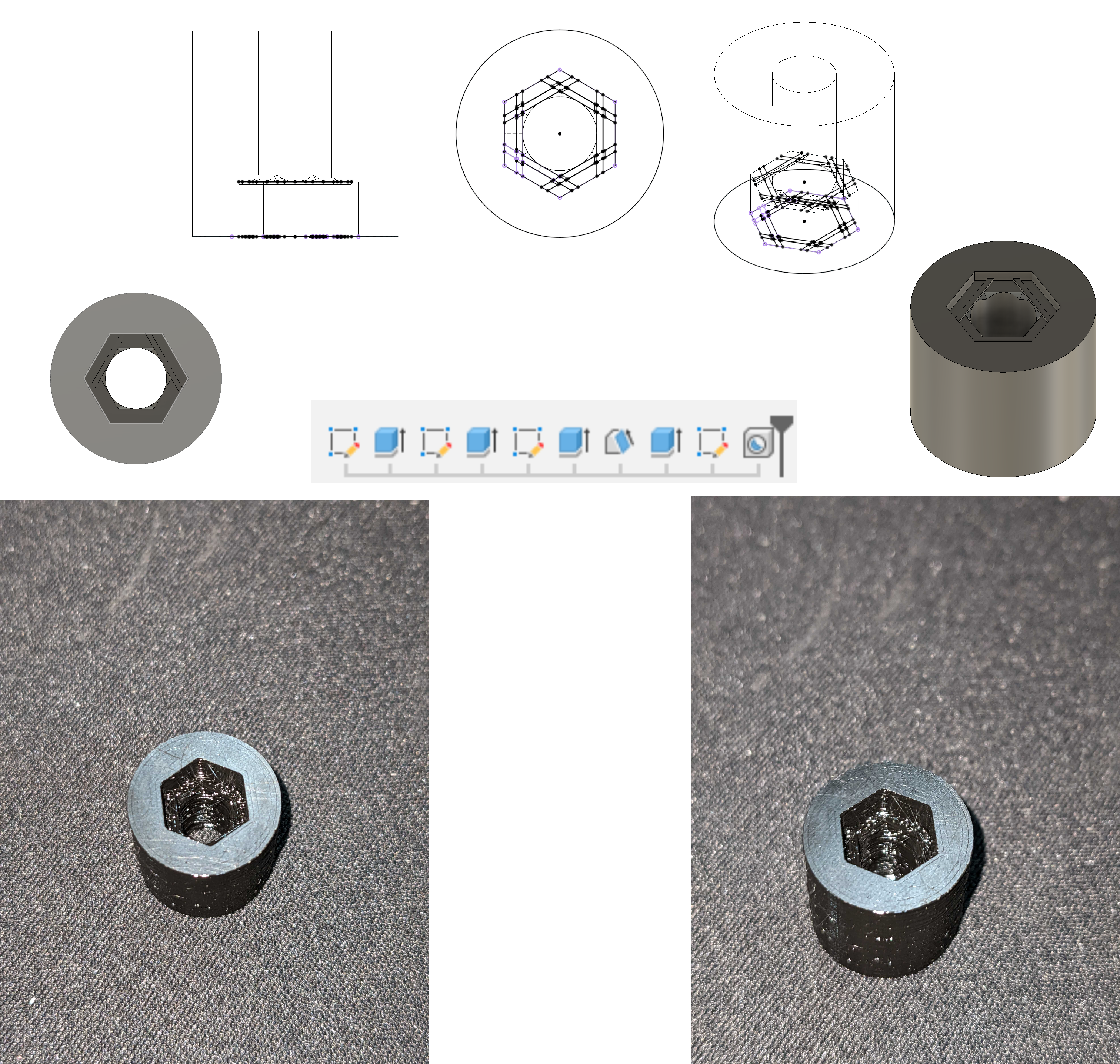
(The feature/sketch count can be optimized I just slapped this together to see what kind of results it could produce)
It looks terrible in the photo but upon inserting the nut and torquing it there was very little compression from those initial bridging layers.
Another thing that helps is inserting a modifier part into prusaslicer and setting the volume between the nut and screw head to 100% infill. When you're trying to position/size this modifier object use part manipulation coordinate input (bottom left) to quickly position these on a part with a lot of screw holes.