Perimeter and layer separation, 0.25 nozzle, PETG
I'm trying to print a small hinge clasp part, and it is separating when put under stress.
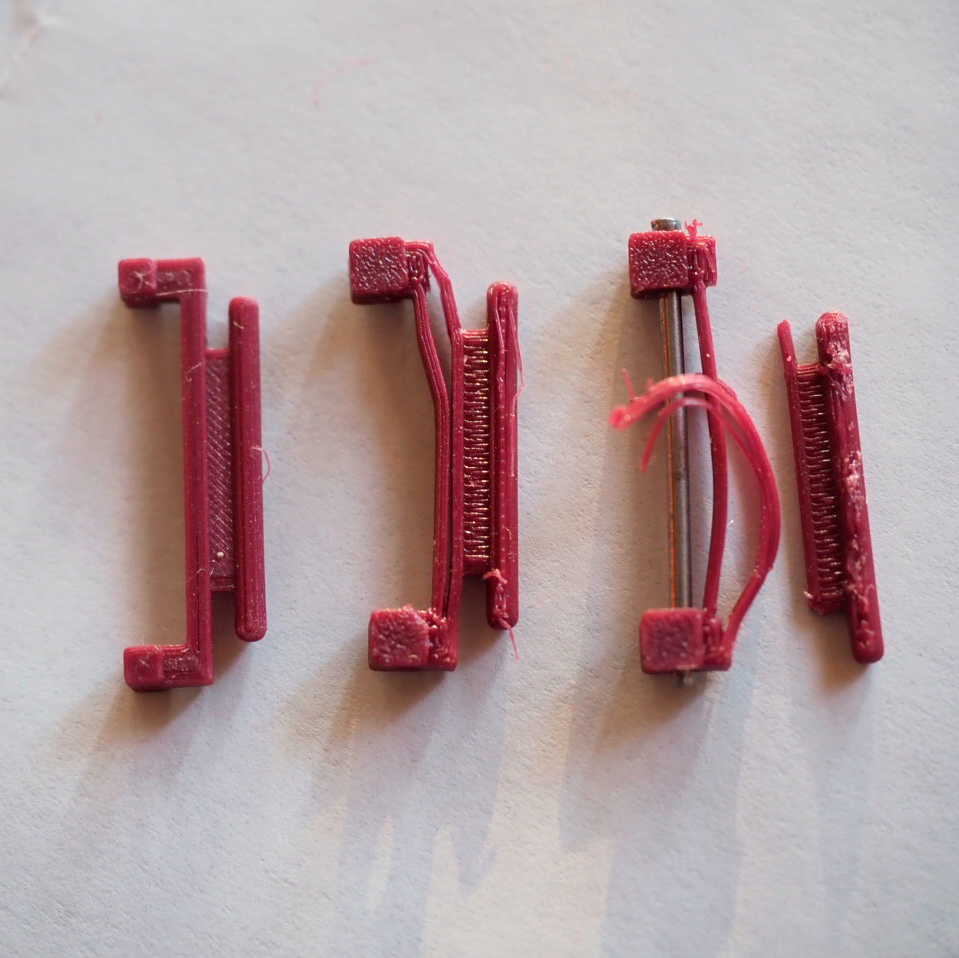
The part is printed with Matterhackers PETG, 0.25mm nozzle, in the orientation shown in the photo.
As can be seen in the photo, when sideways stress to the right is put on the part (it is held on the left by the pin), it appears to separate at the joint between individual perimeter loops as well as layer separation once the loops have pulled away. Is this a problem with not enough material being extruded, too low temps, or something else?
I've increased the temp to 245C to try to get better flow for fusing the individual loops.
Please save your project as a .3mf file
Files > Save Project as
Zip the .3mf and post it here. It will contain both your part and your settings for us to diagnose.
Cheerio,
RE:
@ga
I seen a fair amount of this happening with the Arachne perimeter gen. There are ways to adjust the overlap using the APG. however I don't have a 0.25 installed right now to test that my advice would be sound for your specific use case. But I can say with confidence if you switch to the Original perimeter gen, and set your external perimeter extrusion width to 0.3 that you should see an improved bonded result.
I don't hate the APG, but I've both seen and had many issues with it, especially with the default settings, and I certainly don't think it should be the default PG.
Delamination has been one of the main ones, inconsistent extrusion behavior has been another main problem.
Anyway I think if you leave the project set up as it is now and change the external perimeter, and use the classic gen it will help.
RE: Perimeter and layer separation, 0.25 nozzle, PETG
@R&D Thanks, I will try that. Do you know when the APG became the default? Are you seeing the same sorts of problems with other diameter nozzles (I switch between 0.25, 0.4, 0.6 and 0.8)? I have had some separation issues with other nozzles so may want to switch for them also. What is supposed to be the advantage of using the APG?
The underlying problem is that you are concentrating a lot of stress in a very small area, by all means follow the suggestions above they should help a little, but spread the stress in the original design...
Instead of a flat bar connecting the pin to the mount flare or chamfer the attachments so the right angles are removed.
Counterintuitively a narrow rib along the opposite side of the mount to add material to the zone of tension might help...
This is a basic engineering problem so a while spent researching stresses and stress reduction will probably give you several approaches to try.
Cheerio,
RE:
@ga
Do you know when the APG became the default?
They changed it as of the 2.5 alpha, by the time it got to 2.5 finial they had made the changes listed below to its behavior. Just something to keep in mind if you use it.
Parameters wall_add_middle_threshold and wall_split_middle_threshold were removed and are set automatically based on extrusion width. This results in better results in cases where the extrusion width of individual features differs (infill vs perimeters, etc).
Parameters min_feature_size and wall_transition_length can now be set in percents, in which case they are calculated based on nozzle diameter. Old profiles containing default values are converted into this percentage-based format, values that differ from the defaults are left untouched as the absolute values.
The original perimeter generator is now called "classic" and you can switch to it in 2.5 and still get the same great functionality you used to enjoy from the previous PG. It's in Print Settings\ Layers and perimeters\advanced, and can also be found on a per object basis under Add settings\Layers and perimeters\Perimeter generator. I mention that because they changed where it was from the testing releases.
I personally still use 2.4.2 because the developers also took it upon themselves to completely screw up the seams in 2.5 for no reason that I can fathom. I have kept up with the changes in the software though in case they should ever fix them. Many users are not happy about it.
Are you seeing the same sorts of problems with other diameter nozzles ?
Yes, so far only with 0.4, 0.5 & 0.6. I haven't had occasion to try it with 0.25 or 0.3 yet. As I mentioned before I'm also seeing extrusion inconsistencies, They are created in the slicer, not by the nozzle. We have to take into account the changes in functionality I quoted from the release notes for 2.5 above. I don't believe it's working as it should, and while I mentioned there are ways to make it act like we would want it to, it's more of an art form then anything, it acts differently based on the area and shape its applied to, also it can change after you get it where you want it, (not a good thing) by then simply moving or rotating the part, your results can change be different, dependent on the settings you used when setting up the APG for a specific project. <--- I've have had this happen with several projects.
What is supposed to be the advantage of using the APG?
The advantage is supposed to be, the ability to print superior quality small details using the prevailing technology in FDM\FFF printing. The APG can adjust extrusion widths during the calculations for slicing. So "very basically" you would give it a model and say I want my extrusions to be x.xxmm max size, and x.xxmm min size, and it would look at the model and decide based on the models shape and your specified criteria what to do to best print it, of course we have several settings not just the two mentioned.
The developer of the APG was the Cura development team, it was almost specifically developed for their Ultimaker printers, however the software was open source and showed promise, so Prusa snatched it up Kachuncked it into slicer and made it the default 🤪. My opinion is that APG was still very much a beta software when they did that, and that the 2.5 Final release of PS is still a beta with problems that make it unusable for many projects and new users of the software don't realize what they are into until their projects fail and they find someone that can answer why. Not to mention the Seam problem they created out of the blue and don't seem interested in fixing.
At this time, I recommend using the Original perimeter gen, learning to adjust your extrusion widths manually (for best results) and maybe just playing with the AGP to keep up with it, I think in a couple of years it might be ready, but even then I don't ever see it as a replacement for the OPG, but rather as a compliment to the tools at your disposal. If seams become important in your projects I recommend keeping and using PS 2.4.2.
This is also just my opinion, But so far its not looking like they are trying to fix much of the core functionality in the 2.6 releases but rather just adding more toys. To be fair I am seeing a features I like in these releases but things like the terrible seams make it unusable for my professional use.
RE: Perimeter and layer separation, 0.25 nozzle, PETG
@Diem Thanks for the insights and suggestions.
Counterintuitively a narrow rib along the opposite side of the mount to add material to the zone of tension might help...
I don't understand what you mean by the "opposite side of the mount". The part under tension would be the right (in the photo) side of the stuff that separated, but there's no room there -- the cylinder with rounded ends rotates in tubes that fit around the cylinder ends and fully occupy that space.
@R&D Thanks, that's a help. I think I've had some problems with extrusion inconsistencies also, but not certain that was the problem. In any case, I've changed to Classic/Original and so far so good so will keep that until I find a reason not to.
Add a narrow rib to the left hand side as pictured - it will go into compression allowing the tension zone to spread a little further and so reduce local intensity.
Experiment, the part is only a few grams of material so printing several variations and testing to destruction should quickly improve the design.
Cheerio,