RE: One perimeter wall
Thanks - I do value your input (and your website!).
RE: One perimeter wall
OK... here's a continuation of the discussion. A few caveats:
- These are contrived examples to show the effect of the Detect thin walls setting.
- They are not intended to be a howto guide on achieving good prints.
- These results may or may not print successfully. That is not what I am demonstrating.
In previous examples, I use a 1mm nozzle. The thin wall section is (IIRC) 1mm thick. The wall was thinner than the extrusion widths, so Detect thin walls was necessary to print the side walls.
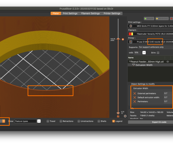
In this example, I'm using a 0.4mm nozzle with 0.4mm extrusion widths with Detect thin walls off. The thin walls are printing as 2 X 0.4mm extrusions plus gap fill in the middle:

In this example, I'm still using a 0.4mm nozzle but with 0.7mm extrusion widths (not recommended, but you can go roughly 2X nozzle size with E3D nozzles) with Detect thin walls off. The thin walls are printing as 1X 0.7ish extrusion. The slicer is getting as close as it can while adhering to my specified extrusion widths.
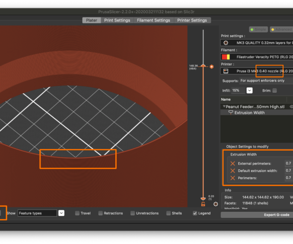
In this example, I'm still using a 0.4mm nozzle with 0.7mm extrusion widths with Detect thin walls on. Because I've enabled Detect thin walls, the slicer can try adjusting extrusion widths when walls are too thin to print with the normal specified number of perimeters. It has used 0.7mm extrusion widths on the thicker parts of the print, but switched to a single 1mm-ish extrusion for the thin walls.
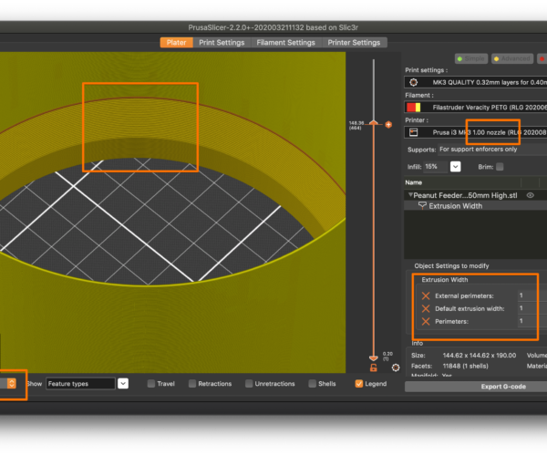
These are the cases where the nozzle and extrusion widths are narrower than the wall thickness. If you use a nozzle and extrusion width larger than the wall thickness, the results are different. In this example, I'm using a 1.0mm nozzle with 1.0mm extrusion widths with Detect thin walls off. The slicer throws an error warning about the thin walls.
If I turn Detect thin walls on, the slicer can vary extrusion widths, so can print the thin walls:
This result is interesting:
- The slicer stuck to my specified 1mm extrusion width for vertical surfaces that can be printed with the specified number of perimeters.
- The slicer has adjusted the width up considerably to print that layer between the normal and single extrusion walls (the dark orange layer).
- The slicer has adjusted the width slightly (down?) to print the thin wall as a single extrusion.
My take on it is that Detect thin walls is not "print smaller if needed" but "detect if a wall cannot be printed using the desired perimeters and adjust extrusion widths up or down to print if possible".
The end result is that we cannot give you one definitive answer that will apply to all cases. Whether or not to use Detect thin walls must be determined based on:
- The thickness of walls you are specifying.
- The perimeter extrusion width you have specified.
- The nozzle size you are printing.
This is a good example of where 3D printing is more like cooking than engineering. The exact recipe depends on the exact ingredients. Sometimes you either have to design your part to print using just-so parameters, or adjust your settings to accomodate a print with specific characteristics.
and miscellaneous other tech projects
He is intelligent, but not experienced. His pattern indicates two dimensional thinking. -- Spock in Star Trek: The Wrath of Khan Unfortunately,…
RE: One perimeter wall
Thanks - I do value your input (and your website!).
Glad it's useful. I think these notes are going up as a page soon!
I am not 100% certain, but I think Detect thin walls is a bit more complicated in that it will reduce extrusion widths based on your specified nozzle size, not your specified perimeter extrusion width. This means you can use a smaller nozzle at unusually wide extrusion widths, yet DTW can still go narrower to really thin walls. So extrusion widths tie into it, but so do nozzle sizes. I'm trying to contrive some tests to confirm this.
Of course, the magic of using a small nozzle to print wide walls goes away when you realize it also restricts you to low layer heights, thus negating any benefit to printing thin, semi-transparent walls.
and miscellaneous other tech projects
He is intelligent, but not experienced. His pattern indicates two dimensional thinking. -- Spock in Star Trek: The Wrath of Khan Unfortunately,…
RE: One perimeter wall
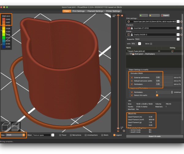
Thanks for all this. Here is simple model, but a bit more than a cylinder. The model wall thickness is 0.9mm. I'm using the 0.6 nozzle, and if I set the extrusion thickness to 0.9, number of perimeters to 1, and 'detect thin walls' off, then it won't slice properly (lots of gaps), despite model wall = extrusion thickness. You have to switch DTW on for it to work.
If I then lower the extrusion thickness to 0.85 it will slice fine without DTW enabled, but it will be much thicker than I want (look at the material used, nearly 2g). If I enable DTW, then it slices a thinner wall thickness (material used just over 1g). So it seems to be putting in a whole perimeter extra without DTW enabled. I can't seem to get a one perimeter wall without DTW.
RE: One perimeter wall
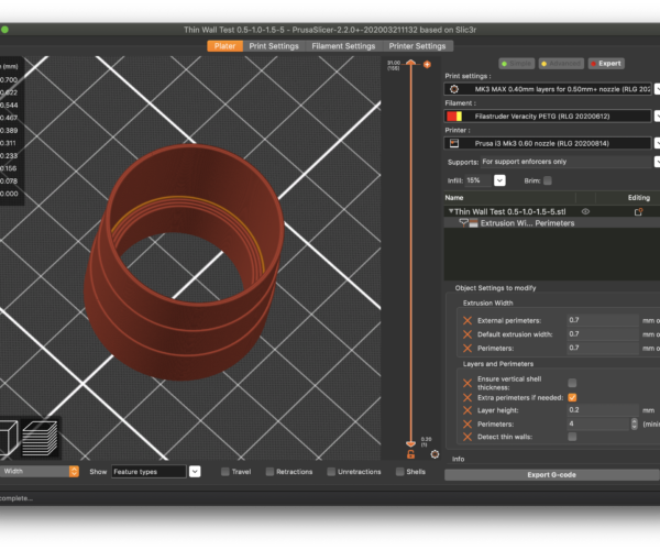
Here's a really contrived demonstration. I created a model with wall thicknesses of (from bottom to top) 5, 1.5, 1.0 and 0.5mm. I sliced it with a 0.6mm nozzle using 0.7mm extrusion widths and Detect thin walls off:
With DTW off, the slicer:
- Used the specified 0.7mm extrusion width throughout.
- Approximated the 1mm width with 2 extrusions (must test to see how this prints).
- Didn't try the 0.5mm thick section.
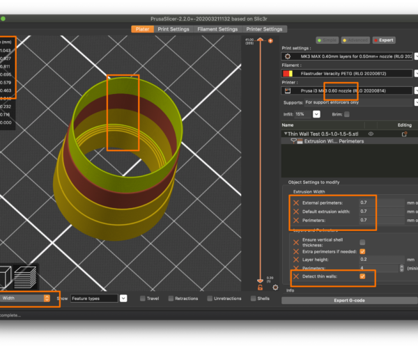
Turning Detect thin walls on yields:
With DTW on, the slicer:
- Use my specified 0.7mm extrusion width on thick walls.
- Increased extrusion width to print the 1mm segment as a single extrusion since multiple perimeters won't fit.
- Decreased extrusion width to print the 0.5mm segment as a single extrusion since a single perimeter using the specified 0.7mm width won't fit.
I've attached the part & settings as a 3MF project file for anybody wanting to play along at home.
and miscellaneous other tech projects
He is intelligent, but not experienced. His pattern indicates two dimensional thinking. -- Spock in Star Trek: The Wrath of Khan Unfortunately,…
RE: One perimeter wall
[...] Here is simple model, but a bit more than a cylinder.
Looks like it didn't attach. Anything you attach has to be in a ZIP archive. Try saving your part & settings as a 3MF project file, zip it and attach it to a response.
and miscellaneous other tech projects
He is intelligent, but not experienced. His pattern indicates two dimensional thinking. -- Spock in Star Trek: The Wrath of Khan Unfortunately,…
RE: One perimeter wall
[...] If I then lower the extrusion thickness to 0.85 it will slice fine without DTW enabled, but it will be much thicker than I want (look at the material used, nearly 2g). If I enable DTW, then it slices a thinner wall thickness (material used just over 1g). So it seems to be putting in a whole perimeter extra without DTW enabled. I can't seem to get a one perimeter wall without DTW.
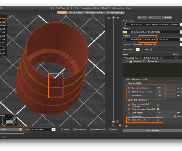
This gets back to "cooking versus engineering" I think. Here I'm using an updated test model (with a 0.25mm thick wall added):
The slicer:
- Prints thicker walls at my specified 0.45mm.
- Fakes it on the 0.5mm thick section (the top layer printed in this pic) and prints a single 0.45mm perimeter.
- Gives up on the 0.25mm section and generates nothing.
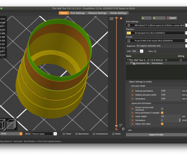
Turn on DTW and you get:
The slicer:
- Prints thicker walls at my specified 0.45mm.
- Increases extrusion width for the 0.5mm thick section (the 2nd from top dark orange section in this pic) as a single perimeter.
- Decreases extrusion width for the 0.25mm thick section (the top green section in this pic) as a single perimeter.
I think the answer to your quest is that widths up and very close to your extrusion width can print as a single extrusion with DTW off, but the slicer will fake it using your specified extrusion width. You told it to use that width, after all. With DTW on, the slicer has permission to vary widths up or down to try to exactly match the actual wall thickness.
I've updated the 3MF with the 0.25mm section.
I'm printing this monstrosity with a 0.4mm nozzle now, will be curious to see how these settings translate into the real world.
and miscellaneous other tech projects
He is intelligent, but not experienced. His pattern indicates two dimensional thinking. -- Spock in Star Trek: The Wrath of Khan Unfortunately,…
RE: One perimeter wall
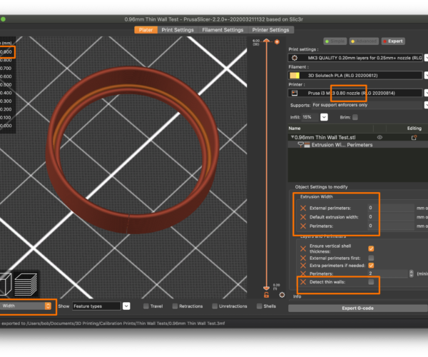
Here's a small part with 0.96mm thick walls printed with a 0.8mm nozzle at default extrusion widths with Detect thin walls off printing a single perimeter.
Not trying to be obtuse. There's no one answer and so much depends on the specifics of what you're printing. I think it's really a trial-and-error process. I'm trying to come up with one description that fits every example and failing. The lesson to be learned I think is that if you want to do this often, consistently use thicknesses that you have tested to print with your nozzle and widths.
Sample attached.
and miscellaneous other tech projects
He is intelligent, but not experienced. His pattern indicates two dimensional thinking. -- Spock in Star Trek: The Wrath of Khan Unfortunately,…
RE: One perimeter wall
sorry, I forgot to zip it. Here is the file for the model that I was talking about above.
RE: One perimeter wall
Here's a small part with 0.96mm thick walls printed with a 0.8mm nozzle at default extrusion widths with Detect thin walls off printing a single perimeter.
Not trying to be obtuse. There's no one answer and so much depends on the specifics of what you're printing. I think it's really a trial-and-error process. I'm trying to come up with one description that fits every example and failing. The lesson to be learned I think is that if you want to do this often, consistently use thicknesses that you have tested to print with your nozzle and widths.
Sample attached.
Attachment removed
Try flipping DTW on and off, and check out the amount of material used - it changes, so I'm not so sure that the wall thicknesses are the same.
RE: One perimeter wall
DTW is going to give you the closest match to the wall thicknesses in your design. Here's what I'm getting with DTW on:
When you refer to "gaps" are you by any chance referring to the z-seam line near the top? If I change the location of the seam, that moves around. It's not a defect and will close up when printed, but it will create a blemish. You can move it around with the seam location setting.
I can only account for the difference in weight being DTW allowing more exact matching of the extrusion widths. I'm not sure what is wrong the the result you are getting with DTW enabled. The difference in filament used either way is ~1g, or $0.04 using the values you entered. This thing is tiny! I wouldn't over-think optimizing it.
and miscellaneous other tech projects
He is intelligent, but not experienced. His pattern indicates two dimensional thinking. -- Spock in Star Trek: The Wrath of Khan Unfortunately,…
RE: One perimeter wall
For this model there is not a problem with DTW enabled, it is just an example to illustrate the issue. I don't care so much about the weight of this one either, but my other parts do get about 20% heavier due to the thicker wall with DTW off, or have horrible gaps/artefacts with DTW enabled.
I pulled up the original tall part and see what you mean about the defects at the top with DTW enabled. I think you're running into a situation where you have to design the part with the printing parameters in mind. I did exactly that with my birdfeeder parts, but I was going for much chunkier parts. Sorry I can't help with anything more with PrusaSlicer. I have no idea if another slicer would help much more.
and miscellaneous other tech projects
He is intelligent, but not experienced. His pattern indicates two dimensional thinking. -- Spock in Star Trek: The Wrath of Khan Unfortunately,…
RE: One perimeter wall
I noticed in your project that you have entered zeros under the extrusion widths - what does that do? Result in default values?
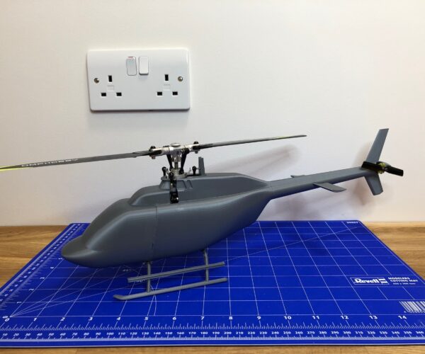
Thanks again for spending the time to look at this. I've been using Fusion 360 and an i3 Mk3s to design and print parts for a scale r/c helicopter. Despite being a complete noob I have managed to get some good results both with the standard 0.4 nozzle/PLA and a 0.6 nozzle with XT/XT-CF20, so credit to PS and Prusa for that. Although neophyl may consider the boom to be unfit for this method of manufacture, it actually prints quite well. I am just trying to get the walls a bit thinner to save weight. The fuselage shell is another 'thin wall' print that I am trying to optimise as it also suffers when DTW is enabled, and I would like to get to one perimeter using the transparent XT.
RE: One perimeter wall
I noticed in your project that you have entered zeros under the extrusion widths - what does that do? Result in default values?
Exactly, but with a twist. If you specify 0 for extrusion widths, PrusaSlicer will select values based on your current nozzle size. This lets me use a single Print Settings profile with multiple nozzles, avoiding a lot of redundant configuration.
[...] I am just trying to get the walls a bit thinner to save weight. The fuselage shell is another 'thin wall' print that I am trying to optimise as it also suffers when DTW is enabled, and I would like to get to one perimeter using the transparent XT.
Have you considered doing this as a multi-part print? Printed vertically, it's not going to have a lot of strength, even with CF20. It will be weak along the long axis, but very rigid in the others. If you can separate the long shaft from the front/top part, more options might work.
Are you familiar with Colorfabb's LW-PLA? It's a temperature-sensitive PLA that will print with different density at different temperatures. You might be able to use it for things like aerodynamic panels and cowls, reserving the stiff CF20 for frames that can be printed flat, and thus be very rigid and strong. This brings up the interesting possibility of printing your part as a rigid frame with snap/screw-on panels for airflow.
and miscellaneous other tech projects
He is intelligent, but not experienced. His pattern indicates two dimensional thinking. -- Spock in Star Trek: The Wrath of Khan Unfortunately,…
RE: One perimeter wall
Just another thought: You might be better off printing some of these parts as solids, but with minimal perimeters and minimal infill. Perimeters add most of the strength, but a single perimeter is only going to be as strong as adhesion between layers. Also, holes or slots can actually increase strength as they add perimeters. I'm imagining your tall part printed as a solid, but with a hole running the length (height) of the part with perimeters to add strength. Nothing says you can't print with multiple materials (frame and reenforcing rod) that fit together.
and miscellaneous other tech projects
He is intelligent, but not experienced. His pattern indicates two dimensional thinking. -- Spock in Star Trek: The Wrath of Khan Unfortunately,…
RE: One perimeter wall
Thanks for the tip on the extrusion widths. The tail boom is surprisingly strong with PLA at 1.0 thick, with CF20 at 1.4 or so it is very strong - enough so that I am looking to make it thinner! Printed vertically I'm guessing that it requires less post processing to achieve a good finish and certainly less support material. I've also used CF20 for the frame, and XT is great for the fuselage as it is less brittle than PLA. For an airplane I might consider the LW-PLA, but really it is just a less dense PLA with a proportional reduction in strength too.
RE: One perimeter wall
Hi all,
the matter does not seems so easy, look at this issue on GitHub:
https://github.com/prusa3d/PrusaSlicer/issues/7973
It seems to me that some sort of grey zone exist between enabling or disabling the "Detect thin walls" feature. A feature that is not designed to meet the user intents during 3D modelling and slicing processes.
All this leads to undesired slicing results.
