G Code viewer shows layers as dark blue can I change the color on the screen?
I don't want to change the color of the part, but the dark blue for each layer is difficult for me to see. How does one change the layer color on the display? Ideally I'd like to see the layer beneath it as one color and the displayed layer as an easily resolvable color difference. With the current dark blue on my screen I cannot even resolve the layer print direction. Perhaps those with young eyes can see this, but, my eyes cannot resolve the subtle color differences.
PrusaSlicer G-code Viewer 2.5.0 on Linux. One would think there would be some color controls, but I don't see any.
RE: G Code viewer shows layers as dark blue can I change the color on the screen?
G-code Viewer-2.6.0-alpha4 is much better. The colors used are much easier to resolve. It also shows the feature type which is helpful.
What I learned was the bridge infill did not come off when I removed the supports, and it has resulted in my part having insufficient clearance for the mating part. The 3d model has 0.25mm clearance, but the slicing didn't maintain that. I will have to see if I can get variable height slicing to work.
RE: G Code viewer shows layers as dark blue can I change the color on the screen?
What I learned was the bridge infill did not come off when I removed the supports, and it has resulted in my part having insufficient clearance for the mating part. The 3d model has 0.25mm clearance, but the slicing didn't maintain that. I will have to see if I can get variable height slicing to work.
Bridge infill does not come off. That is part of the model itself, not support material.
I don’t think variable layer height will fix the clearance issue. I think the design will simply require more clearance.
Can you share the models? It may be easier to understand exactly what the issue is if you do.
RE:
I have a FreeCAD model, stl and 2D drawing. I'll attach the stl file and pdf, which should be good enough to see what I am trying to do. The read head is 14mm wide and is held by this plastic bracket. The bottom holes are for M4 screws to hold the bracket to the lathe saddle.
Seems I am a new enough member that I cannot attach an stl file even though it is 205.3KB.
RE:
Let's try a pdf file... Guess an stl file is not allowed. Images appear to be attachable.
RE: G Code viewer shows layers as dark blue can I change the color on the screen?
Let's try a pdf file... Guess an stl file is not allowed. Images appear to be attachable.
The 3d model has 0.25mm clearance, but the slicing didn't maintain that. I will have to see if I can get variable height slicing to work.
The way you are printing it, you have 6.1 mm from the print bed to the first flat surface, then 14.25 mm. If you're printing this with 0.2 mm layer height, 6.1/0.2 = 30.5. The printer can't make a half layer, so it either would print as 30 or 31 layers (not sure which). If it prints as 31 layers, then the lower part will be 6.2 mm thick.
Variable layer height may fix this, or also just try a lower layer height in general?
My original thought from earlier relates to the supports. Whenever you support something, it's not going to be perfect. The slicer leaves a gap, on purpose, between support and part layers. If they didn't, you couldn't remove the supports later. I'm not sure how exactly the slicer is doing this gap, which way it's leaving it, but if it just leaves the supports slightly low, then the part filament is going to "droop" a little bit.
RE: G Code viewer shows layers as dark blue can I change the color on the screen?
I get a 13.83mm gap at the root of the U, at the wide side and 13.48 gap on the narrow side. The read head is 14.00 mm. It seems the slicer is off by one filament width.
I may have done something silly though. I tried rotating the part 180 degrees, but I ended up with some weird angle which was not on a major axis. That is probably the reason for the varying gap. There's no way to read out the rotation angle in the slicer and correct it by typing in a number - that I know of.
The issue with printing the U up are that all the horizontal holes need to be machined/modified. (Hole sag.) If I have to machine too much, I may as well make the part from aluminum. It's not like it is hard, but it is annoying. If the slicer was better, one would think they could come on target better. Guess this is part of the process of learning what these printers are and aren't good for. Definitely allowed me to converge on something that fit on my lathe.
As I'm typing, a version with variable spacing is printing. I made sure the part was on the major axes. Not sure it will be much better. Worst case, I guess I could take a pass with an end mill, but I was hoping to avoid that.
Attached is the stl model, zipped.
RE: G Code viewer shows layers as dark blue can I change the color on the screen?
I may have done something silly though. I tried rotating the part 180 degrees, but I ended up with some weird angle which was not on a major axis. That is probably the reason for the varying gap. There's no way to read out the rotation angle in the slicer and correct it by typing in a number - that I know of.
Not that I am either. They don't have an absolute angle that I've found.
However, there is the "Place on Face" button. Click this, it highlights flat faces, click a flat face and it pops that face to the bed.

Also a trick I didn't realize originally, if you're not aware: When rotating, you see a ring with lines. These lines are common multiples of angles. If you are rotating, run the cursor over this ring. It'll snap to multiples of 5°, which really helps when rotating a part by 90° to make sure it ends up flat on the bed.
RE: G Code viewer shows layers as dark blue can I change the color on the screen?
I get a 13.83mm gap at the root of the U, at the wide side and 13.48 gap on the narrow side. The read head is 14.00 mm. It seems the slicer is off by one filament width.
Looking at your U-shaped part in PrusaSlicer, at 0.2 mm layer height, I see that the layer with the lowest flat section is layer 31, and the upper layer of the U-gap is layer 103. That means the gap is layers 32-102, which is 70 layers. 70*0.2 = 14 mm. So the slicer is taking the 14.25 mm gap, and making it 14 mm.
There's more though. If we look at the upper part of the gap, we see the top layer of support. The uppermost layer of support is layer 101:
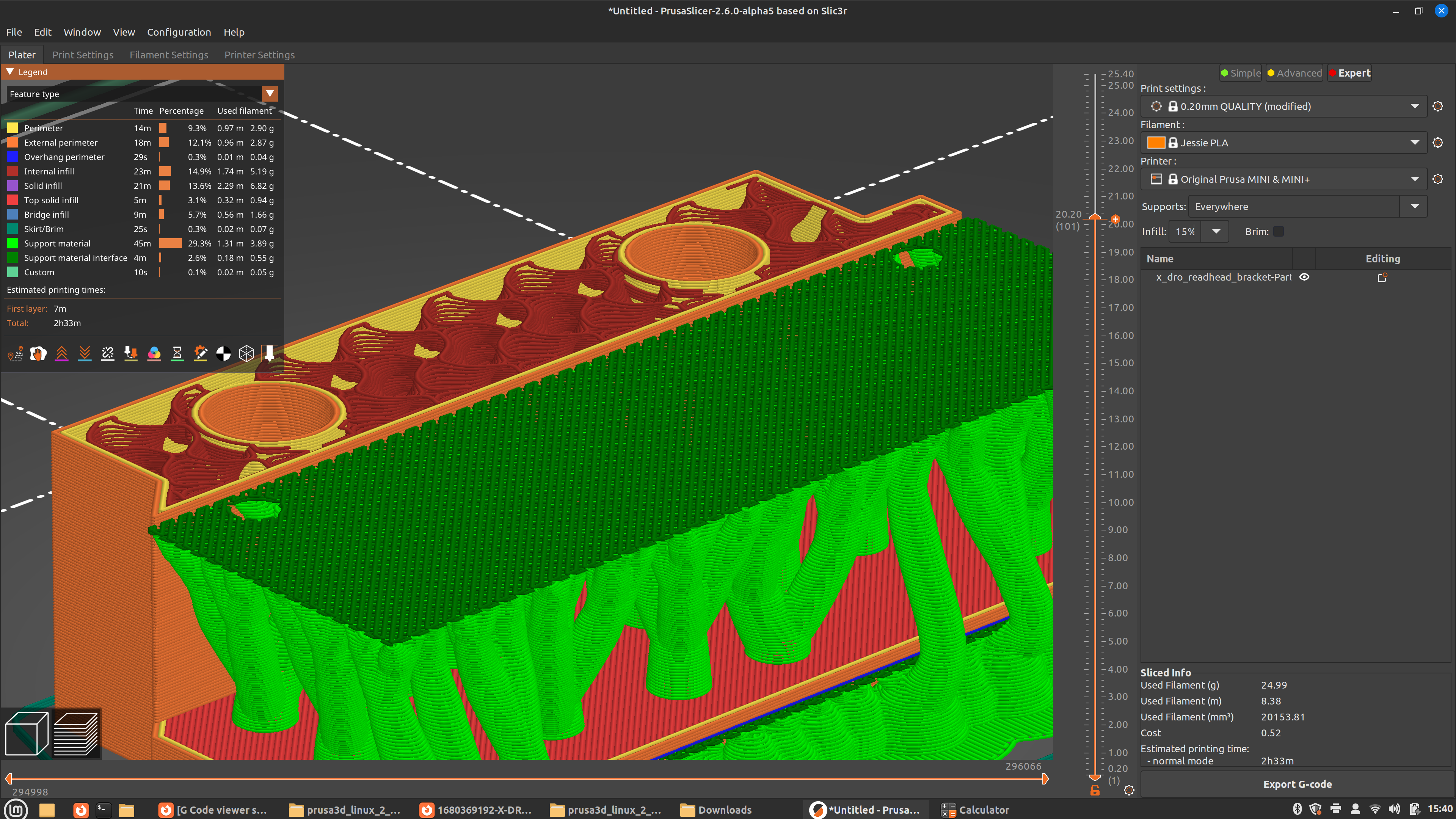
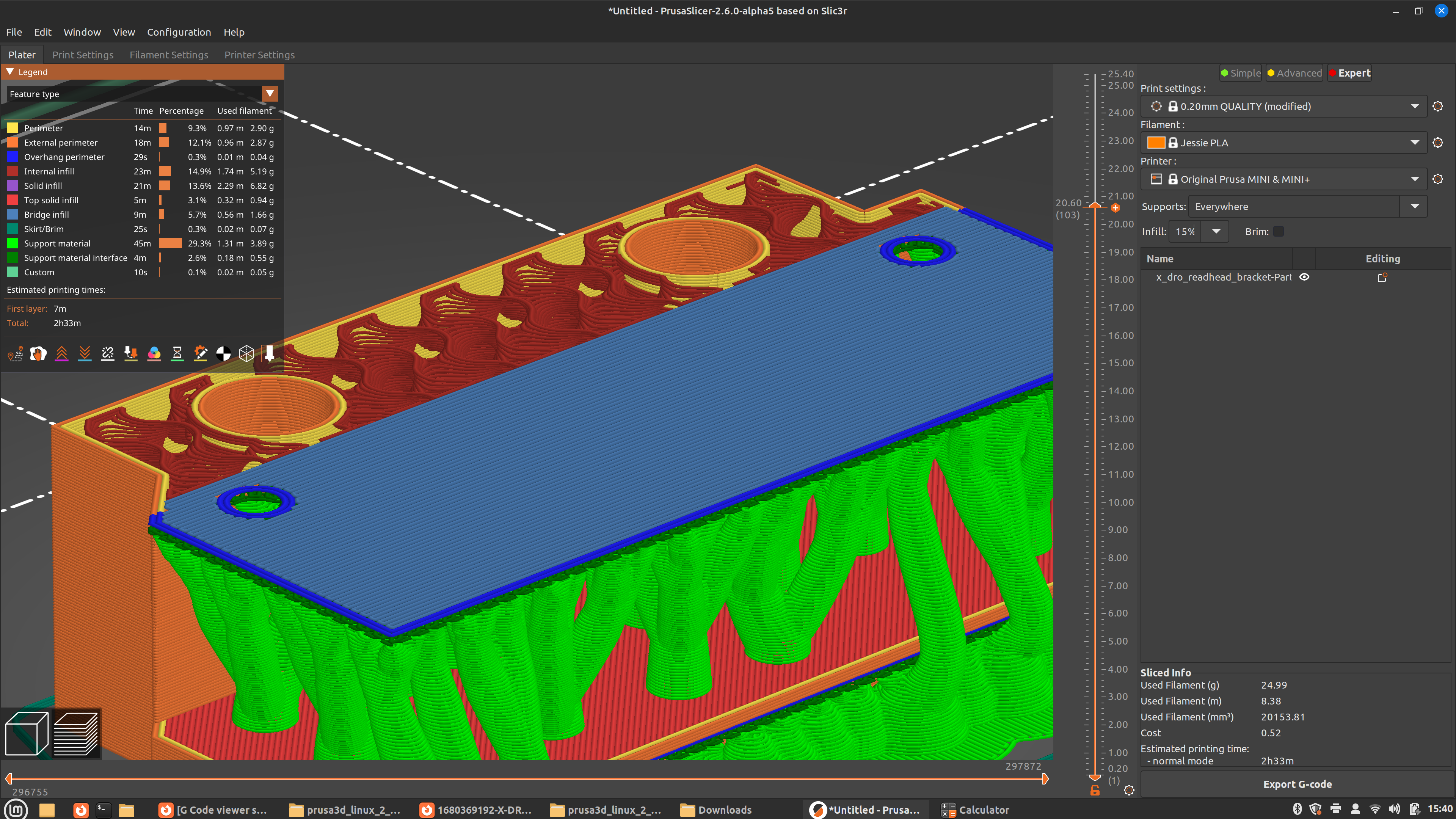
Look at layer 102, and we see there is no support material added, but we aren't adding the layer for the upper part of the U yet either. It's an empty layer.

Then in layer 103, we have the top of the U. However, there's an empty layer, 0.2 mm thick, below this layer, as seen in the above screenshot. So this supported layer (layer 103) is actually going to take up the height of two layers, because it's going to droop down until part of the filament rests on top of the supports which were layer 101.
So take 14 mm gap from the slicing, subtract another 0.2 mm to account for support droop and you're down to 13.8 mm, which is almost exactly the 13.83 mm you measured at the root end of the U. I'm guessing the other side was 13.4 mm due to the part flexing during the printing process? But depending on exactly what this is supposed to do, you can probably just bend that apart enough to shove the mating piece in, if the gap was >14 mm at the root end.
If you go to Print Settings > Support Material > Options for Support Material and Raft > Top contact Z distance you can change the default 0.2 mm support gap. Options are 0.2 or 0.1 mm (detachable) or 0 mm (soluble). I've not tried 0.1 mm myself, but it will likely make it harder to break off the supports, especially on a large flat plane. No gap will give you the best tolerances, as no gap means no droop, but you'll need to have a MMU so you can print supports in PVA or similar and dissolve them in water afterwards.
What if you change the gap width of the model to 14.5 mm instead of 14.25 mm? Is a very tiny gap an issue here?
RE: G Code viewer shows layers as dark blue can I change the color on the screen?
Thanks for taking a look at this. Since this piece has taken so long to print - I have run out of enthusiasm. 5 tries are enough. I took the last version - which I printed using variable layers (didn't do a very good job at it and took a long time) on its side and just stuck it in my mill. I'm disappointed that the slicer is violating the clear space and even more disappointed there is no way to tell the slicer there are constraints. So I milled the channel open to the required 14.25mm. That is a 0.25mm total gap, which is sloppy in my machinist mind.
So my problem is solved and I can proceed with the installation. I learned that organic supports are not supported in variable layers. I also learned that variable layers doesn't work all that well and did what I would consider unintelligent. It printed too many individual thin layers rather than slightly adjusting a few to conform to the requested layer height from the bed. These thin layers bubbled and had incomplete coverage. Unless I learn a lot more about them, I won't be using them again.
I was frustrated a bit by all this, thinking it would have been just as easy to actually machine the part out of aluminum.
My experience level with 3d printing is minimal, so it makes it tough to absorb all the terminology or to comprehend tuning.
Unfortunately the root gap was 13.83 which obviously is a no go for a 14mm part. As for going to a wider gap, it's not preferable, as the part would bend if bumped and there was a big gap. I can try increasing the gap and slicing it just to see what happens. Perhaps I can learn from that.