Enhancement request: sharp edge detection
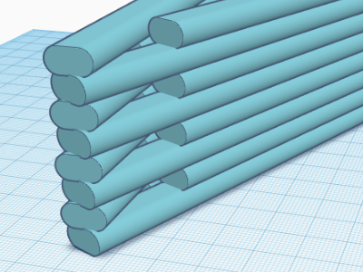
I am frustrated in trying to print an object with a sharp edge (as in the trailing edge of an airfoil). When the nozzle turns a sharp corner in the XY plane, the line of filament globs up, because there's a region near the corner where two filament widths are squeezed into a smaller width.
Thin wall detection isn't useful. If I try it, PrusaSlicer generates an edge that is separated from the part by a gap.
Modeling my part to have a radius isn't feasible either. If I have to sand the trailing edge of an airfoil to be sharp, it is no longer the correct airfoil shape.
The slicer is capable of sharper edges (as sharp as the nozzle diameter) if it could only know how to handle it.
So I suggest the following. If an angle at a corner is less than, say, 20 degrees:
- When the nozzle gets to that corner, it stops extruding material after turning the corner until it is clear of the filament it already extruded.
- Or, stop extruding before the nozzle gets to the corner to make room for the extruded line after turning the corner.
- Additionally, reverse the order on each subsequent layer. That is, on even numbered layers, use rule #1 when turning a left corner and rule #2 when turning a right corner. On odd numbered layers, use rule #1 when turning right and #2 when turning left. This assumes that the extruder goes round the same corner in the same direction on every layer.
The edge would have tiny gaps and bridges in it every other layer. That's fine, and at least the edge can be as sharp as the nozzle diameter, and remain nice and neat, without making globs of plastic.
The trigonometric calculation for the size of the gap is simple enough; I actually put these gaps into my model to see what PrusaSlicer would do, with poor results. The best solution is for the slicer to handle the situation properly.
Illustration attached.
RE: Enhancement request: sharp edge detection
Usually filament pile-up is Linear Acceleration (aka K-Factor). There is a simple test generator available on the Marlin website. Once you find the proper value, it goes here:
M900 K{if printer_notes=~/.*PRINTER_HAS_BOWDEN.*/}200{elsif nozzle_diameter[0]==0.6}18{else}25{endif} ; Filament gcode
RE: Enhancement request: sharp edge detection
@tim-m30 - would you explain to me how acceleration would have anything to do with inability to print a sharp vertical edge? Basically in a sufficiently sharp corner, the filament is folding over on itself, regardless of acceleration or speed. No amount of acceleration will do what I describe in my proposal at the start of this thread. What am I failing to understand?
As for the test pattern, I assume you're referring to this: http://marlinfw.org/tools/lin_advance/k-factor.html - correct?
Should I be proposing this to Marlin instead?
RE: Enhancement request: sharp edge detection
I think I understand what you desire, but there's a physical issue with the simple fact the nozzle orifice is circular. That sets a minimum radius, no matter what your do with it. A 0.4 mm nozzle can't print a 0.01 mm line. So when two 0.4 mm lines converge at some small angle, the best it can do is overlap. The workaround is to use a smaller diameter nozzle, as this affords a smaller minimum radius.
As for a feature request to ask the devs to make adjustments to the flow are these locations,
Here's an example of two converging 0.42 mm lines, and the resulting slice: one might argue the small line between is is excessive, and the gcode planner certainly doesn't lay the lines down in any order that makes sense to me, but the "sharp end" is limited by the nozzle diameter. The tip of the V is actually several strokes not shown in the preview, but done for what I assume to be minimizing excess material (exactly what you say is missing).
In any case, the best way for you to move forward is for you to create a test case that clearly shows what your concern is, demonstrably, with stls, 3mfs, and even gcode with images print that shows the problem you want solved. Then post a defect report or feature request over at Github.
RE: Enhancement request: sharp edge detection
@tim-m30 - I don't know if you saw my attachment in my first post (I didn't realize how to insert an image at the time), but it illustrates what I want.
All I want is for sharp corners to be as sharp as the nozzle diameter allows. To do that, the lines can't fold over themselves when the nozzle turns the corner. Instead, to avoid globbing, the line must be discontinuous at the corner, alternating the position of the discontinuity on each layer, like this:

That's as sharp an edge as possible with a nozzle that can't print narrower than its diameter.
Thanks for the advice. I can provide STLs and prints that show the problem along with my suggested solution in the image above. I don't know enough about gcode to offer a solution, though. And until I read your reply I wasn't aware there was a github repository where I could make suggestions.
RE: Enhancement request: sharp edge detection
And here's what K-factor does: and why it is important to calibrate it to your printer setup. Note those thick areas? That is pile-up caused by the nozzle extruding at rates different than ideal, generally due to hydrostatic pressure at the start and stop of print moves; the time the nozzle is accelerating and decelerating. If K-factor is off, a stroke will have thin or thick ends. So your sharp edge gets distorted by a simple mechanic, even when the slicer is doing it's job. Prusa defaults to 30 for most MK3 printer filament profiles... and this test on my printer shows 25 is a slightly better number.
RE: Enhancement request: sharp edge detection
@tim-m30 - thanks, I see the slight difference between K=25 and K=30 for your printer. I'll try that test; it's definitely worth doing and making any correction to my custom G-code before reporting a problem on GitHub.
I suspect, however, that the problem I have isn't pile-up for a single strand, it's the fact that the extruder continues extruding around a sharp bend when it should leave a gap to prevent re-extrusion over a strand it just laid down. At a sharp bend, there's a small region where two strands are co-located rather than side by side.
RE: Enhancement request: sharp edge detection
If I read the gcode correctly (I may be wrong), but it does handle the overlap area differently depending on settings, almost as if it really isn't printing the regions at 100% flow. But with the gcode viewer I use, its hard to tell for sure what the flow is doing and when.

