What is causing this and how to deal with it.
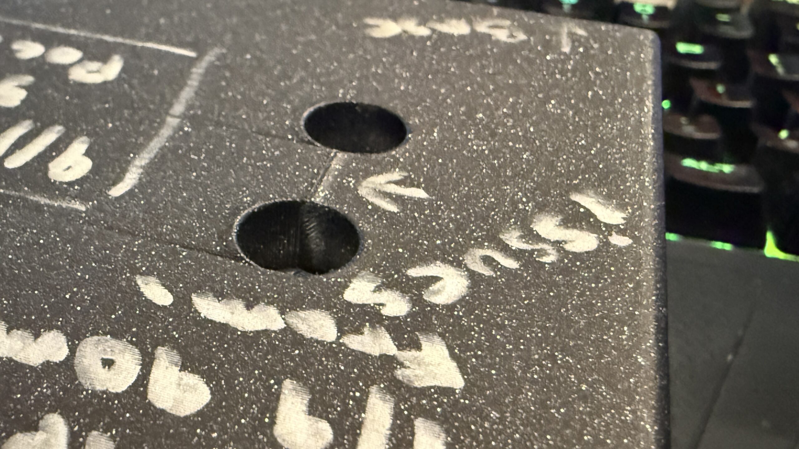
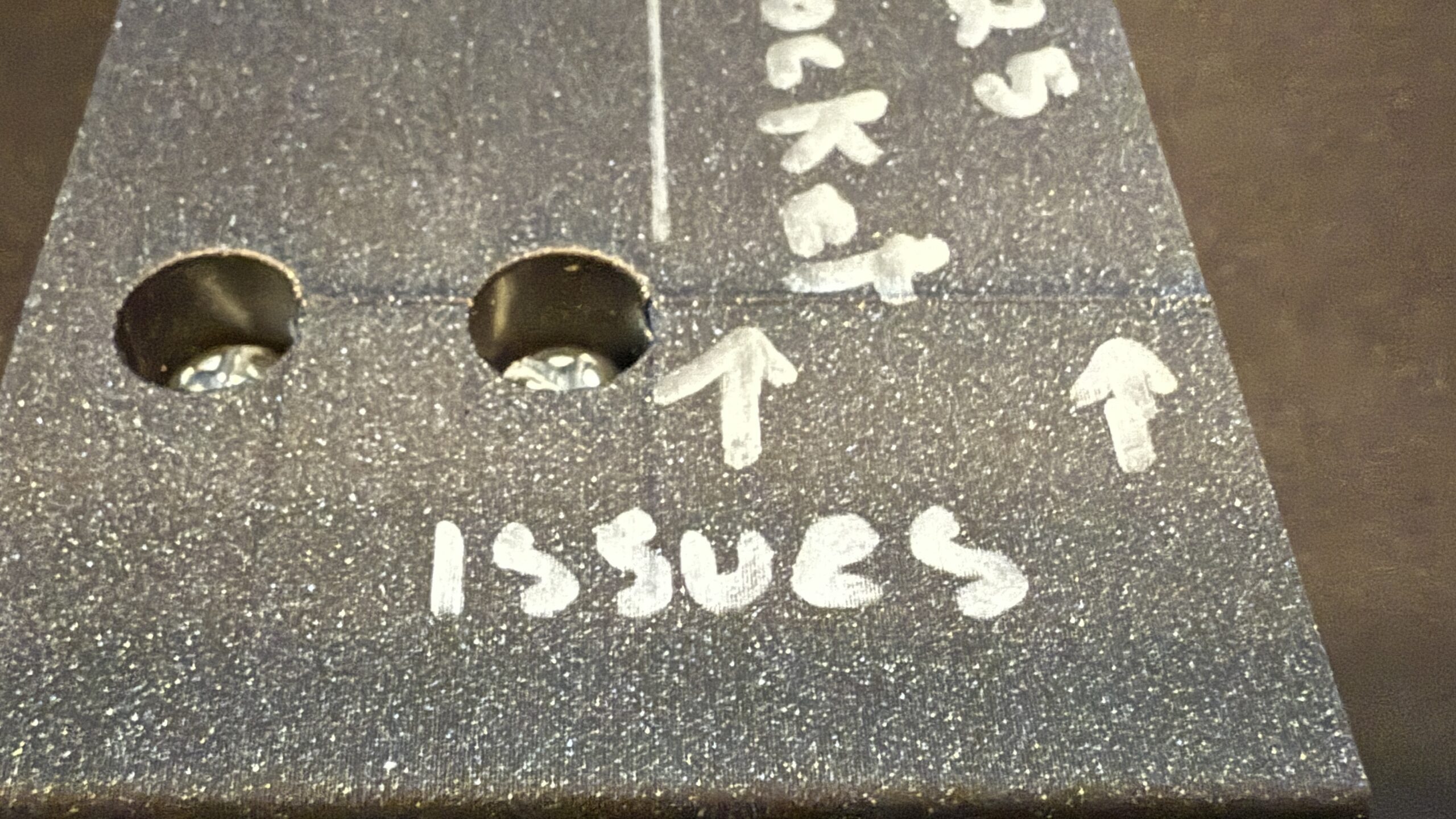
Take a look at this pics and tell me what you make of this "bump" in my prints.
The issue is using my Core One, Prusament PLA, bone stock .20 mm SPEED profile, 15% infill, with HF0.4 nozzle.
All the pictures I'm going to show you, were accompanied by what I can only describe as a bang/thud. Never, ever heard anything like this sound from my printer before. The one shot with with the sharp corner and steep z-axis change, the noise was very loud. Like OMG my printer is broken loud. The others were pretty subtle, but noticeable.

Hopefully you can see them with this iCloud link.
Is the the slicer allowing the head to come in contact with the print? Is that what I'm hearing?
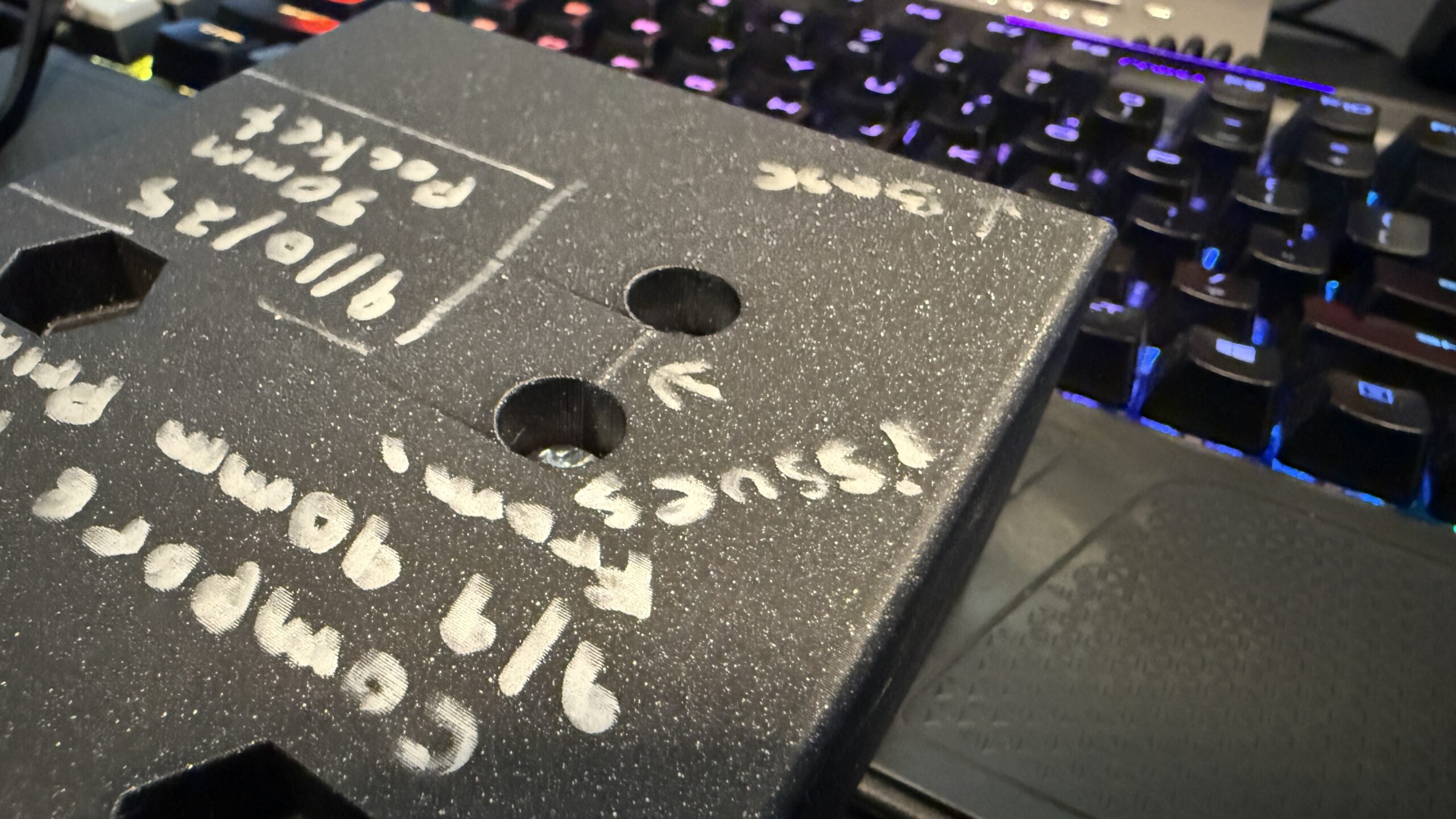
If the pics are in order, the first 2 you can see the hump between the two holes, the next 4 are the same export just flipped 180° in PrusaSlicer. Those have the hump all the way to the top. So just flipping the job give different repeatable outcomes. The last is the pic with the god awful sound.
How do I stop it?
RE: What is causing this and how to deal with it.
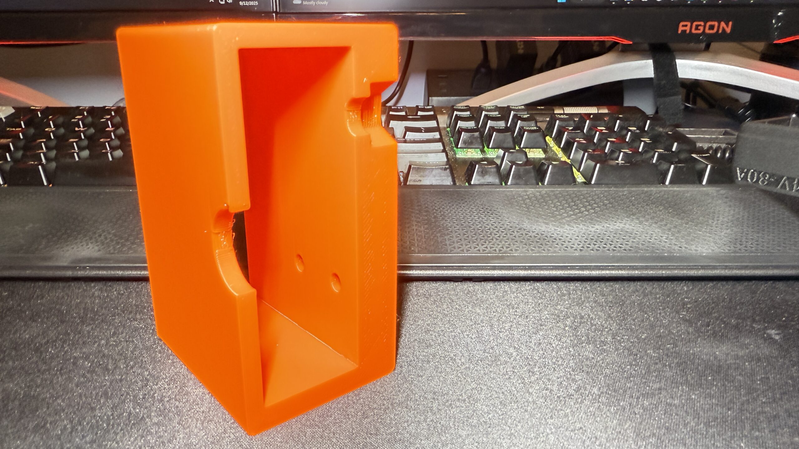
Just ran another test, with Avoid crossing perimeters: Checked and Supports Everywhere.
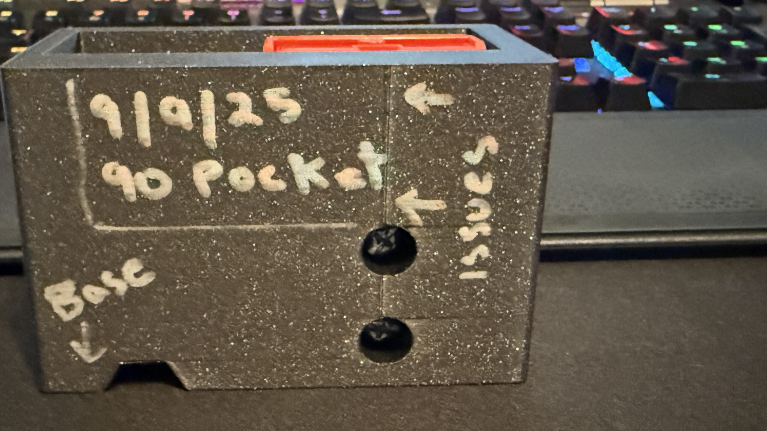
No change. Orange does make it a lot more noticeable.
I'll keep trying.

RE:
Is the heatblock and nozzle inserted correctly and the thumbscrews are tight? That is, the heat block is not extending below the fan shroud and it's not loose? I had this happen when the screws worked loose and the heat block and nozzle were "floating/colliding" into the print.
I can't see the photos. They appear as broken links.
RE: What is causing this and how to deal with it.
Okay let me see how I can get you guys some pics. To answer your question, I would assume so? Everything else is flawless only these two 3mf files that exhibit this issue.
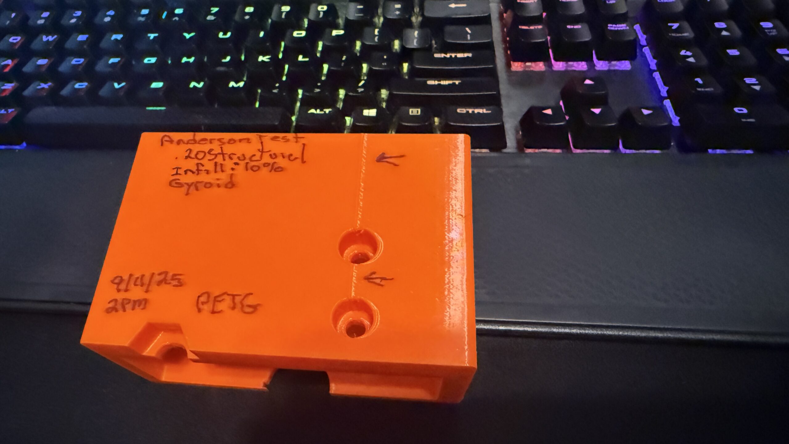
I've got a test running using these parameters.
0.20 Structural
Supports: None
Infill: 10%
Fill pattern: Gyroid
It's only 37% done, dog slow but I don't see this hump any more.
You https://share.icloud.com/photos/053MIyFjpwOmU-TPE-P_nj03g
Let me know if you can see them now.
RE: What is causing this and how to deal with it.
No images showing up ... post them to the website, it is simple and easy to do and the image will never go away like most external links end up doing.
RE: What is causing this and how to deal with it.
I think I got it 🙂 The print from yesterday that I thought was fine was not. No change.
RE: What is causing this and how to deal with it.
This is yesterdays test print. I have a video and you can see the printer transition layers at the exact point of the problem.
Then you can see the back of the print. No issues there.
RE: What is causing this and how to deal with it.
Dropbox link with FreeCAD project file and thought I'd give a export of the test as a stl file to the slicer vs 3mf. See if that had any baring. It's printing now.
Dropbox Link to FreeCAD Project and Exports
See if anyone can spot anything I'm doing wrong.
RE: What is causing this and how to deal with it.
Just stopped the print. It's very near identical.
I'm so new at this, just don't know where start looking where the problem is introduced.
My gut says it's the Slicer, the printer is just doing what it's told.
Latest print pics and I've exported the G-code and put it in the Dropbox folder. I'd have to bet, if I knew anything about this code we'd find it was telling the printer to do something funky at this location. Guess I'll be learning some knew this weekend.
So much for new pics, server keeps throwing an error when I try to upload them. I'll try later. I'll throw the pics in the Dropbox folder.
RE: What is causing this and how to deal with it.
Keep those images of yours out of the way. Enter the project into the slicer, slice it, and then select 'Save as 3mf'. Then zip the 3mf file and upload it here so we can see your settings as well. However, if you think your project is secret and no one should see it, then you will have to handle it yourself. However, at first glance, it looks like an improperly chosen seam position. Check the settings and try 'aligned'.
RE: What is causing this and how to deal with it.
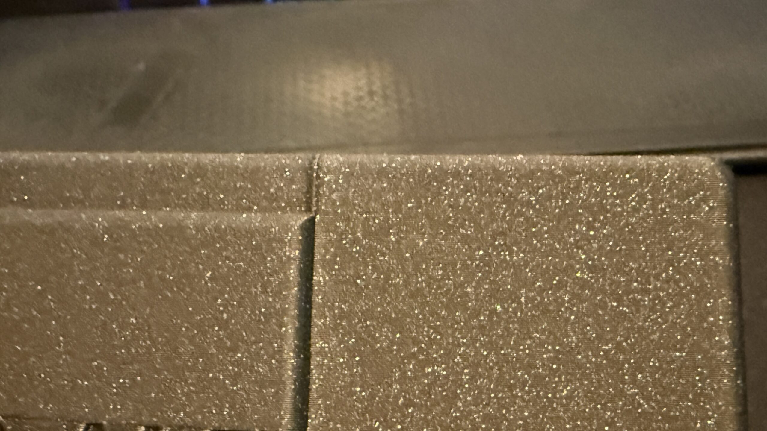
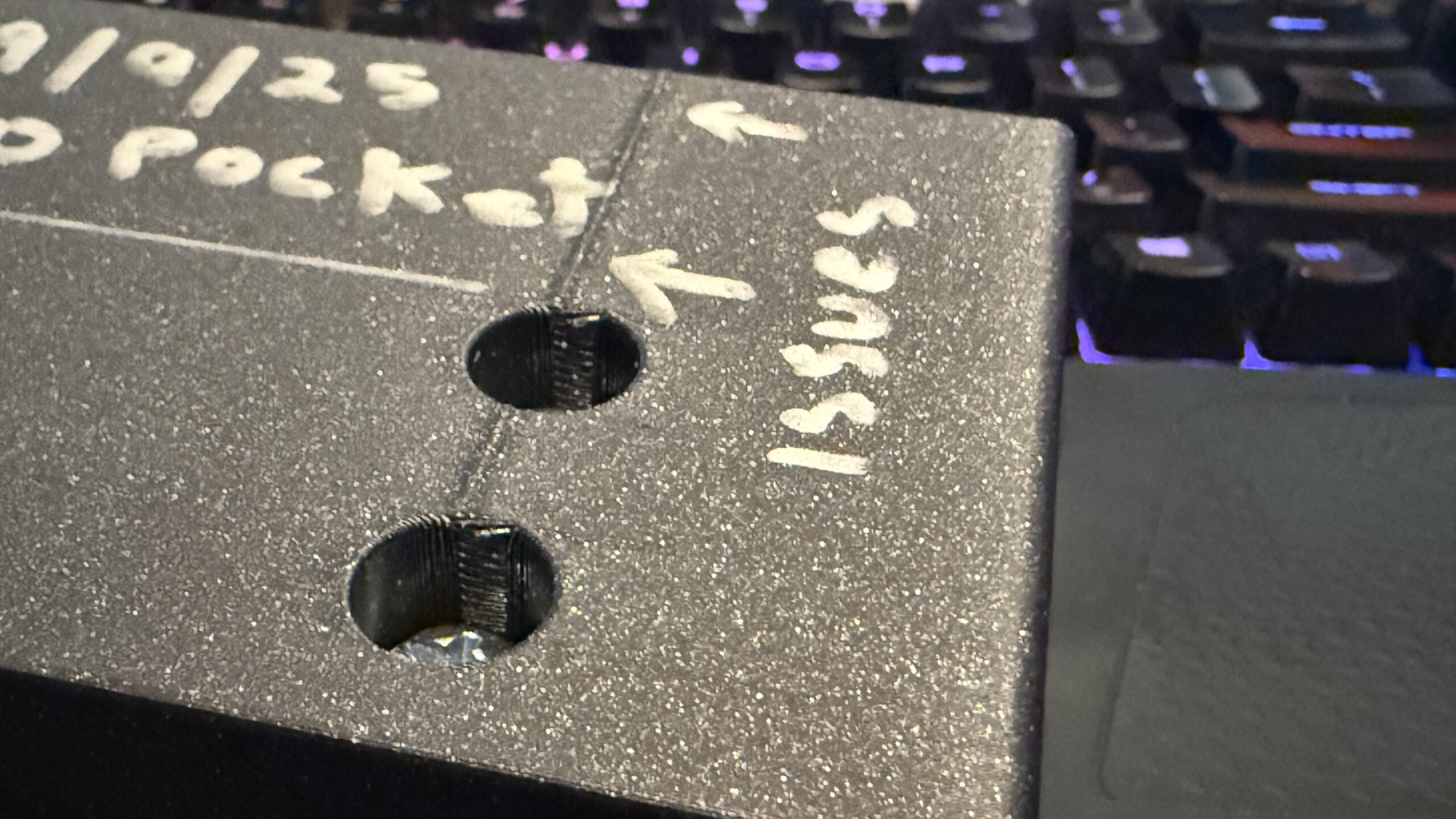
I am going out on a limb here but I would bet that you printed this part oriented with the face with the cutouts facing the build plate (i.e. the bottom most picture of the black part). If I am correct, then most likely what you are seeing is the "seams" where each layer begins and ends. From the appearance I would bet that the slicer setting for "seam position" (Print Settings -> Layers and perimeters -> Advanced) is set to rear meaning you are going to get a nice vertical alignment of seam "pimples" on the rearmost surface of the part (the other possibility is "aligned" but the slicer should have tried to hide the seam in a corner then.
If I am correct in my assessment, then there are several seam settings that can impact this. First, (assuming PrusaSlicer) make certain you are in either "normal" or "expert" mode (top right corner of the slicer window the mode is a "pulldown" selection. In these modes there are several settings that affect seam position (aligned, random, nearest) and one called "scarf joint placement.'' The first setting will do nothing for the appearance of the seam except change where the slicer stops and starts each layer. The second changes the way in which the layers are extruded with a "tapering" of the end of the layer (a scarf joint as used in woodworking) to eliminate the hard stop/start that causes the visible seam artifact.
There are other thing that can be done to minimize visible seams (temperatures, retraction settings, etc) but my bet is that you can get perfectly acceptable results with just the seam settings on most parts.
Good Luck,
Steve
RE: What is causing this and how to deal with it.
Can you guys get to the Dropbox folder? I just dropped the 3mf file that generated the Orange prints.
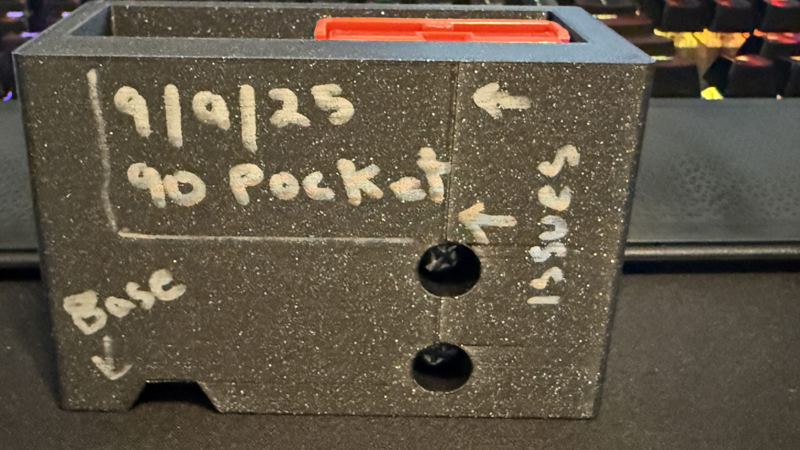
The first 2 pictures where the only ones printed with the hex opening as the top "furthest from the build plate". They showed one seam, only between the 2 Anderson connector mounting holes. If you look close you can see the text "base" scribed with Sharpie indicating that surface was on on the build plate. B kinds of looks like a 3, sorry.
All other prints had the end with the M8 Hex bolt head on the built plate. Those prints the seam started at the top of the 1st Anderson mount hole but continued all the way to the top.
Going to see if I can find this seam position setting.
Project is no secret, I'll post/share anything you guys ask for.
RE: What is causing this and how to deal with it.
Why do you keep shoving that damn Dropbox at me, which requires a registration I'm not interested in? Below the text submission box on this forum, you'll find a button 'Select file'. Select it, and in the window that appears, find and choose the zip file you surely created according to my previous post, click 'open' and that's it. I remind you again that the 3mf file must be 'zipped' otherwise the forum won't accept it.
RE: What is causing this and how to deal with it.
Hope I'm doing this correctly. I looked at the Advanced -> Seam position and it's set to Aligned.
RE: What is causing this and how to deal with it.
Not exactly an apples to apples comparison since: 6.4.0-alpha firmware, PrusaSlicer 2.9.3, 0.4HF Obsidian, 0.25 BALANCEDk, 10% Gyroid, Prusament PETG. The rest are just the default settings. No crashes with the infill and the only seam is between the two screw holes. Not going to do anymore tests because don't want to eat up anymore filament but have you tried with setting the seam to 'Random'? Or perhaps adjusting the Seam gap distance?

RE: What is causing this and how to deal with it.
Try printing this. Don't move the object in any way, the rotation around the Z axis is there intentionally to move the seam to one corner where it won't be as noticeable. Or you can paint the seam anywhere you want where it won't be as noticeable.
RE: What is causing this and how to deal with it.
@miroslav-h4
Printing now, will let you know what I end up with. I really do appreciate your time! Thanks mate.
RE: What is causing this and how to deal with it.
@hyiger
Very similar results when I flipped it 180° on it's X. Seam, if that's what I'm dealing with, only appeared between the 2 Anderson connector mounts.
I've got @miroslav-h4 project printing now. Fingers crossed.
Thanks for trying!
RE: What is causing this and how to deal with it.
@miroslav-h4
It's just about to start the 2nd Anderson mount. I think you may have done it? I can notice that it no longer pauses (and makes some adjustment) as the print head makes it run of the perimeter. It's super linear, just as it was went it was printing below the mount.
Master, what can I take away from this? Was the placement and Z rotation just some random values, I'm guessing not. Looks pretty deliberate to the very untrained eye.
As mentioned you can paint the seam where ever you want, for example on an inside wall or try setting to random which will scatter it as dots.