RE: VFA Artifacts on X+Y Straight Edges
Let's inject some hope into this thread. I had very pronounced VFA on my kit machine. Tonight took apart the gantry, motors, pulleys and belts and put it all together again. My most concrete find was signs of chafing on the y axis motor pulley due to misalignment. I put it all together, ran the input shaping and phase stepping wizards and printed a VFA test tower. The result looks very promising. On my previous print, I can feel the VFA pattern with my fingers while on the new one, everything feels smooth. It's always hard to get through on camera, but now the horizontal lines are more visible than the vertical. I'll do more prints over the weekend and see if we're as good as we get for now.
Attached image. New print bottom.

RE: VFA Artifacts on X+Y Straight Edges
Phase stepping worked for me too. I was like 30% and 80% improvement. I don't notice any noise improvement (and haven't measured any significant difference, the noise comes from chamber fans and fast movements of bearings anyways). VFAs tests are also looking the same (worst around 90mm/s, none at low speeds and high speeds from around 200mm/s).
RE: VFA Artifacts on X+Y Straight Edges
Let's inject some hope into this thread. I had very pronounced VFA on my kit machine. Tonight took apart the gantry, motors, pulleys and belts and put it all together again. My most concrete find was signs of chafing on the y axis motor pulley due to misalignment. I put it all together, ran the input shaping and phase stepping wizards and printed a VFA test tower. The result looks very promising. On my previous print, I can feel the VFA pattern with my fingers while on the new one, everything feels smooth. It's always hard to get through on camera, but now the horizontal lines are more visible than the vertical. I'll do more prints over the weekend and see if we're as good as we get for now.
Attached image. New print bottom.
Now this does look promising. Thanks.
Can you expand on the ‘signs of chafing on the y axis motor pulley due to misalignment’ part…I don’t imagine you took pictures, but what exactly should we be looking for here? What exactly was misaligned and how did you correct it ?
RE: VFA Artifacts on X+Y Straight Edges
Let's inject some hope into this thread. I had very pronounced VFA on my kit machine. Tonight took apart the gantry, motors, pulleys and belts and put it all together again. My most concrete find was signs of chafing on the y axis motor pulley due to misalignment. I put it all together, ran the input shaping and phase stepping wizards and printed a VFA test tower. The result looks very promising. On my previous print, I can feel the VFA pattern with my fingers while on the new one, everything feels smooth. It's always hard to get through on camera, but now the horizontal lines are more visible than the vertical. I'll do more prints over the weekend and see if we're as good as we get for now.
Attached image. New print bottom.
So you moved the pulley closer to the motor, right? According to the manual, I had it about 6.6mm and I moved it to 6.2mm but I will probably move it even closer to about 5.5mm.
The original settings didn't seem right to me.

RE: VFA Artifacts on X+Y Straight Edges
Let's inject some hope into this thread. I had very pronounced VFA on my kit machine. Tonight took apart the gantry, motors, pulleys and belts and put it all together again. My most concrete find was signs of chafing on the y axis motor pulley due to misalignment. I put it all together, ran the input shaping and phase stepping wizards and printed a VFA test tower. The result looks very promising. On my previous print, I can feel the VFA pattern with my fingers while on the new one, everything feels smooth. It's always hard to get through on camera, but now the horizontal lines are more visible than the vertical. I'll do more prints over the weekend and see if we're as good as we get for now.
Attached image. New print bottom.
Now this does look promising. Thanks.
Can you expand on the ‘signs of chafing on the y axis motor pulley due to misalignment’ part…I don’t imagine you took pictures, but what exactly should we be looking for here? What exactly was misaligned and how did you correct it ?
This step. The gap was wrong.
https://help.prusa3d.com/guide/5-corexy-assembly_835522#843334
RE:
That looks promising!
Is it possible to have an explanation on what you changed after removing the gantry and everything?
You said that the motor pulley showed sign of shafting? What does it really mean? It was an issue during first assembly?
Thanks everyone for your inputs!
EDIT: question was answered while I was tipping….
RE: VFA Artifacts on X+Y Straight Edges
This doesn't look like it was printed hot enough (it's matte). Try bumping up the temperature and reprinting to compare
RE: VFA Artifacts on X+Y Straight Edges
That looks promising!
Is it possible to have an explanation on what you changed after removing the gantry and everything?You said that the motor pulley showed sign of shafting? What does it really mean? It was an issue during first assembly?
Thanks everyone for your inputs!
EDIT: question was answered while I was tipping….
Here's the pulley that had debris from chafing. You are looking at the Y axis assembly. I read through the manual and found the pulley was mounted a bit different on the motor shaft. The whole tool head moves different now.

RE:
You said that the motor pulley showed sign of shafting? What does it really mean? It was an issue during first assembly?
You might have missed @baatbyggeren's earlier post in this thread. He found a lot of debris near that back right idler block, and signs of wear on the belt. The linked post has photos.
RE:
This step. The gap was wrong.
https://help.prusa3d.com/guide/5-corexy-assembly_835522#843334
I can confirm the gap is wrong on my printer as well. However, after I fixed it to be more aligned, the belt is now just riding up and down instead of constantly rubbing against one flange. It also didn't affect print quality in any way.
Here's the pulley that had debris from chafing. You are looking at the Y axis assembly. I read through the manual and found the pulley was mounted a bit different on the motor shaft. The whole tool head moves different now.
I'm not sure I understand. You refer to the pulley, but show a photo of 3 idlers? So what was rubbing against what and where? Belt against the motor pulley or belt against some idler?
RE: VFA Artifacts on X+Y Straight Edges
Tonight took apart the gantry, motors, pulleys and belts and put it all together again.
Could you write down what exactly did you take apart and how much? What do you mean by "took apart the gantry"? Did you remove the entire square metal sheet with all parts? Did you remove every single part from it? Did you remove every single idler and put it back again? Or did you just remove the belt, removed the pulleys, left the idlers, plastic and gantry intact and nothing else?
RE: VFA Artifacts on X+Y Straight Edges
Wow. Thst is a heck of a difference.
Let's inject some hope into this thread. I had very pronounced VFA on my kit machine. Tonight took apart the gantry, motors, pulleys and belts and put it all together again. My most concrete find was signs of chafing on the y axis motor pulley due to misalignment. I put it all together, ran the input shaping and phase stepping wizards and printed a VFA test tower. The result looks very promising. On my previous print, I can feel the VFA pattern with my fingers while on the new one, everything feels smooth. It's always hard to get through on camera, but now the horizontal lines are more visible than the vertical. I'll do more prints over the weekend and see if we're as good as we get for now.
Attached image. New print bottom.
RE: VFA Artifacts on X+Y Straight Edges
Could you write down what exactly did you take apart and how much?
I think he means the vertical alignment of the pulleys. Especially on the motor. However, most pulleys can also be adjusted slightly in height.
I described this earlier in the thread.When installed, I used a mirror to observe all the pulleys while moving the print head. I observed how the belt reacted and which direction it moved in.
I adjusted the height of the motor pulley and the others as much as possible so that the belt would not run up to the edge during movement. There is no general setting for this. Everyone has to adjust it individually.
In hindsight, I should have done this before fully assembling everything. It would have made things much easier.
RE: VFA Artifacts on X+Y Straight Edges
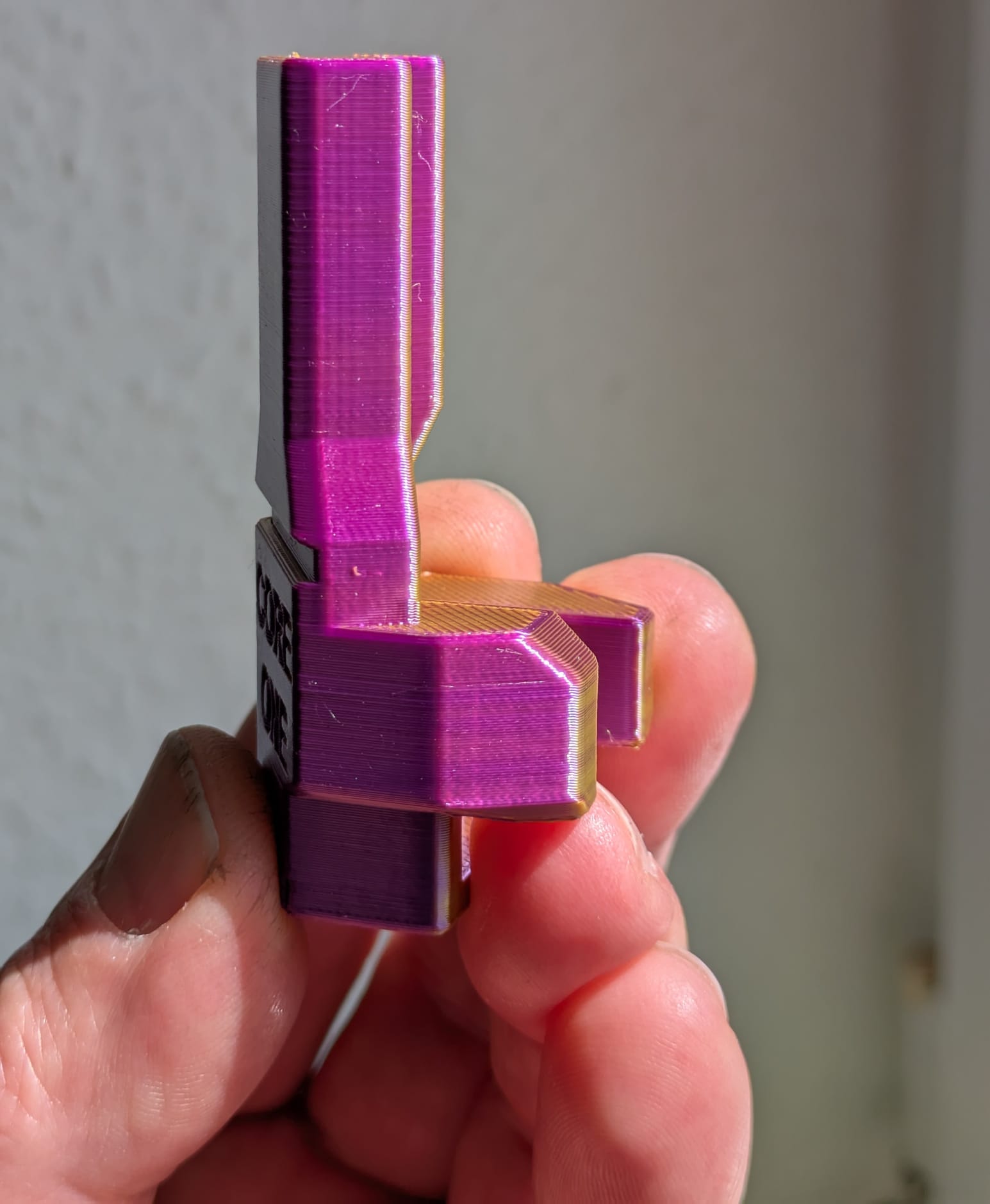


Since someone posted pictures of this print, here are some for comparison.
The glossiest filament I have right now, with the standard 0.2 Speed Pla_Silk profile in the Orca Slicer. The only change is the outer walls to 45mm, and no slower outer walls if the layer time is exceeded.
I took the pictures so that they look as bad as possible in terms of light. In real life, the part looks really good. And to be honest, I could have made the pictures look that way, too 😉
A slightly different angle to the light and the image would look just as good.
In my opinion, you can't expect more from an FDM printer.
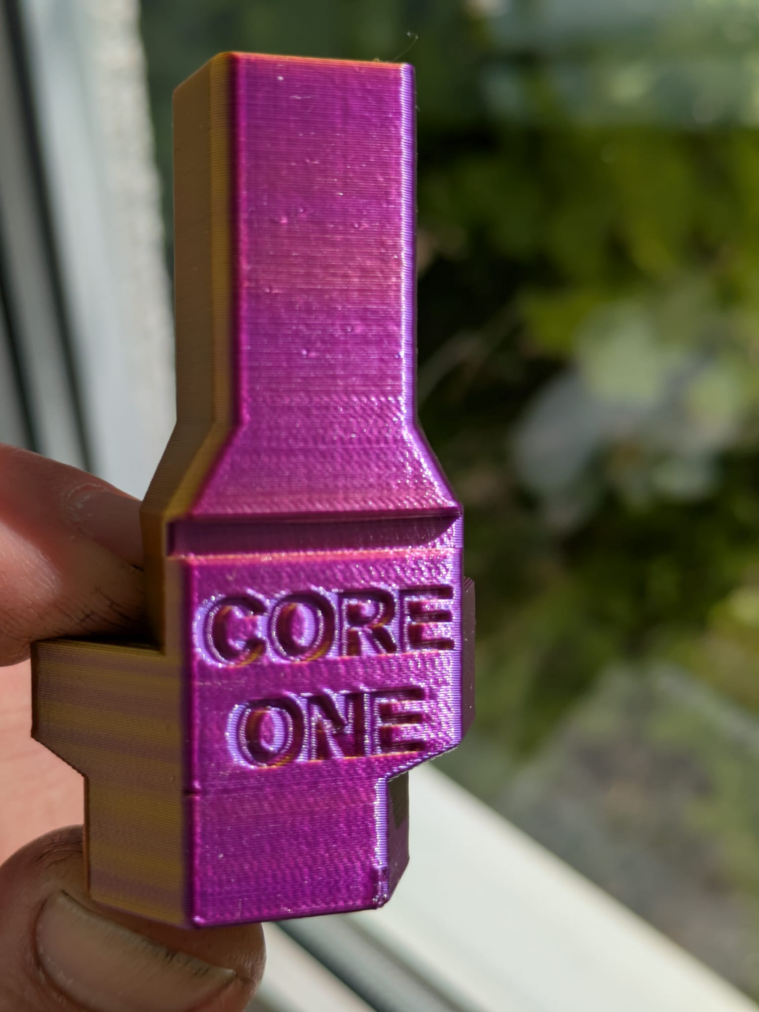
RE: VFA Artifacts on X+Y Straight Edges
Here is I hope better picture. It is just perfect for me.

RE: VFA Artifacts on X+Y Straight Edges
So can this pulley height be adjusted without completely stripping down the gantry?
RE: VFA Artifacts on X+Y Straight Edges
If you have the version of the motor mount with the hole, you already have it.
You can see the motor pulley and loosen the screws. There were early versions that were completely enclosed.
So can this pulley height be adjusted without completely stripping down the gantry?
Yep I have the hole, I can see the grub screw but thought id better check before attacking it.
Just so I'm clear, ideally the belt will sit and run halfway down the toothed part of the pulley, so touching neither the top or the bottom of the toothed part?
Also, I guess I should loosen the belts first, adjust the pulley, then re-tension the belts?
RE: VFA Artifacts on X+Y Straight Edges
Correct, but I would leave the belt taut.Also consider the other pulleys they are also influenced by the height of the motor pulley.
Some of these pulleys can also be moved up or down a little.
Overall, the goal is to ensure that the belt on all pulleys does not run to one side, as much as possible, and that this applies to all possible print head movements.
If you have the version of the motor mount with the hole, you already have it.
You can see the motor pulley and loosen the screws. There were early versions that were completely enclosed.
So can this pulley height be adjusted without completely stripping down the gantry?
Yep I have the hole, I can see the grub screw but thought id better check before attacking it.
Just so I'm clear, ideally the belt will sit and run halfway down the toothed part of the pulley, so touching neither the top or the bottom of the toothed part?
Also, I guess I should loosen the belts first, adjust the pulley, then re-tension the belts?