Skewed XY-Plane (Z Rods, Heatbed)
The xy plane (heatbed) in my Core One is skewed.
Reading here and on Reddit, I noticed I’m not the only one. However, none of the posts (and my hours spent on chat with support) have rendered a solution, so I’d like to document what I’ve done so far. Maybe someone here has a good idea! 😀
I assembled the printer with extra diligence and Jürgen’s (@jurgen-7) helpful steps (thanks a lot!). I kept checking all right angles along the way and double checked the exoskeleton. All perfectly fine.
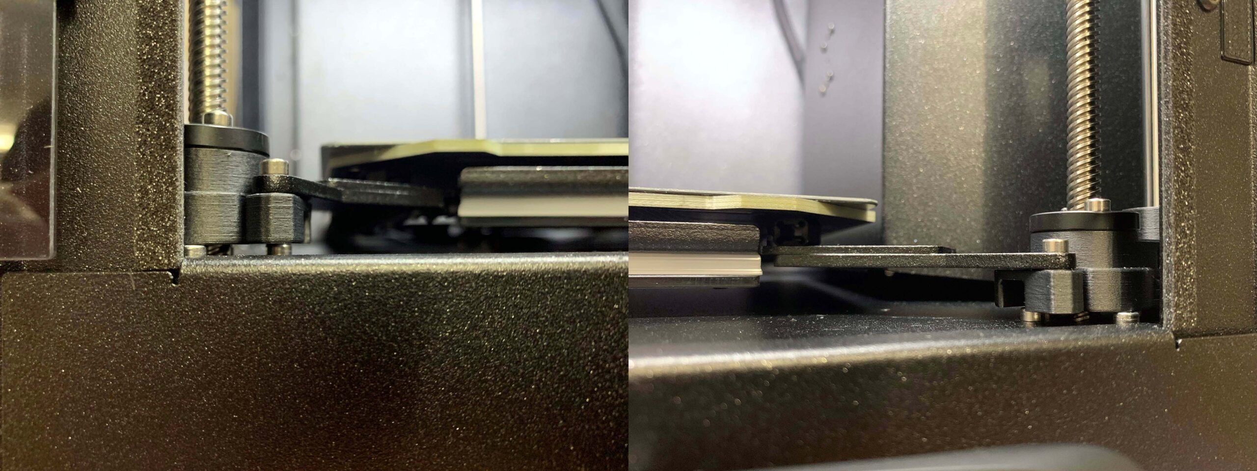
Problem: The front left an front right z screws show 2mm height difference above the carriage right after Z Alignement Calibration once you move them up to z=0. The back screw sits right in the middle with 1mm difference to either side. This means the xy plane is skewed.

I can measure the same 2mm difference from the top and from the bottom.

Further, the skew is not static. Bed leveling can easily compensate at z=0, but the further down the carriage moves (the taller the print), the bigger the difference gets, eventually reaching 2mm.
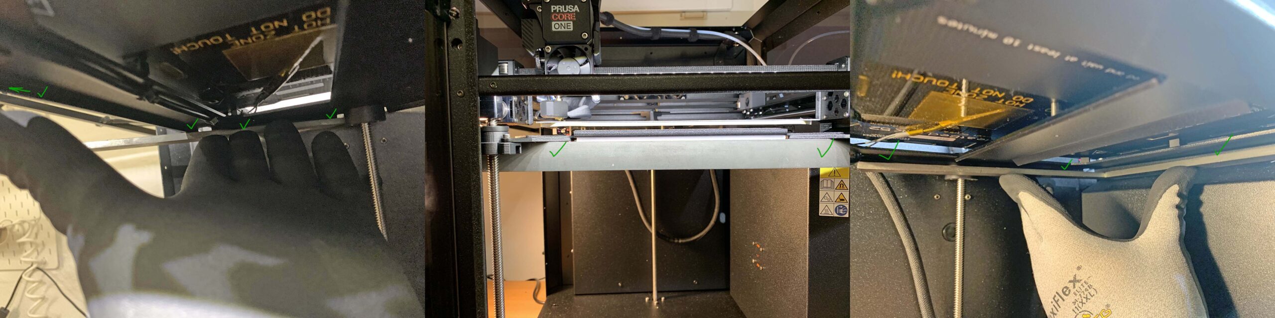
During troubleshooting, support had me print an example to show that this issue does actually affect prints. Notice the height difference of roughly 1mm between the right and left side of the print. Given that I didn’t waste material to print the full height and the printbed width is smaller than the distance between the front z rods, it’s plausible that the difference would add up to the 2mm gap observed above if I would print the full height/could print the full width. (Since the left side is „higher up“, it travels down more, leading to a bigger distance and therefore a bigger print. This is why the left side of the print is taller.)

Some have proposed shims, but they’re a static „solution“ and as far as I can see just move the problem from the top (z=0) to the bottom (z=275). The print will still be skewed. The movement along the three z screws is divergent and the divergence increases during movement from 0 to 275.
What have I tried so far?
Unsuccessful: Manual leveling with motors off at either Z=0 or Z=275. There is no further movement at z=275 because Z Alignement Calibration is working fine. If I adjust for z=0, the skew will be back once I reach z=275.
Unsuccessful: Support suggested I check the Z carriage for unevenness. I removed the four front screws so the carriage would only be held down in one place and therefore „free“ to show any unevenness. Checking with the flattest thing I own (my machinist square put sideways so I can check more than two points in a plane), I didn’t find any unevenness. I may take out the carriage later, but I don’s see what would be different.
Unsuccessful: Swapping trapezoidal nuts between the front left and front right z rods as support suggested. I was quite hopeful, but alas, the right side was still 2mm more than the left even though it is now driven by what previously was the left nut. (Picture pointless…)
Unsuccessful: I put masking tape on all the rods and indicated the front position (6 o’clock from above) to check whether the rods rotate unevenly. I can’t really see anything apart from the z rods tilting slightly to the centre once z=275.

70mm, f11, tripod and timer
Pending: Swapping the motors?
I really struggle to think of what might be the reason behind this. Suggestions greatly appreciated.
RE: Skewed XY-Plane (Z Rods, Heatbed)
Just to be clear and summarise it:
You make it perfectly flat towards the bottom (not the end-stops) and it becomes tilted towards the top (and the other way around)?
So since the black nuts do fit on any leadscrew, the leadscrews should all have the same pitch?
That means it has to be the motors, not spinning perfectly synchronised. Although that would also mean, that it would tilt further and further, when you move the bed up and down via the controls - > axis menu.
I can't imagine the motors only spinning slower/faster in one direction.
How much noise is there, when the bed is moving? Maybe the resistance for the motors is too high?
Since they are controlled by only one connector to the board, can you access the splitter-board, that the 3 motors are connected to? I'd try to swap them around and check if the tilt pitches towards a different leadscrew (probably not).
And the last thing to test, as you say, would be to actually swap the motors around. This could either lead to the problem or solve it, if it's mechanical and you manage to reduce the tension somewhere.
RE:
Hi, I probably have the same problem - the skew is dynamic, when bed was calibrated at bottom after z-calibration, it's not level with hotend plane at the top position. If I manually level it at the top, the skew progressively grew as the bed moved down. I went through similar troubleshooting you described, printed some test prints which showed that it translates to real world inaccuracies in vertical dimensions of the print. I verified that all motors turn synchronously, there are no missing steps.
Finally found out the cause really is incorrect pitch of one of the lead screws. It was clearly the only explanation and when I put both lead screws beside each other and tried to align the threads, you could clearly tell those do not match, when aligned at one of the ends, it gradually fall out of alignment along the screw length.
Currently waiting for new motor to definitely verify the fix.
RE: Skewed XY-Plane (Z Rods, Heatbed)
I don't understand how the height difference can change with a z movement if the spindles rotate in sync.
Would you mind doing one more measurement for me? Measure the bed height at the three spindle positions to the top of the printer from the bed at z=0 and z=250. And maybe also from the bottom of the printer to the bottom of the bed at z=0 and z=250.
If I understand correctly, the difference between these measurements should differ between the three spindle locations.
RE:
Now that's a bizarre find... But it seems to occur in my printer as well!
I compared the heights just between the front left and right spindles -- because they were easily accessible, and because they have the two motors labelled "LEFT". I.e. one from the pre-packaged Mk4s motor kit, and the extra one that was added for the Core One. The extra motor & spindle might come from a different batch?
Measured the height between the base plate (which serves just as an arbitrary reference plane) and the struts which carry the trapezoidal nuts:
- Run the Z calibration, driving all motors into their end stops:
Z = 274 mm, left = 15.9 mm, right = 15.7 mm. - Move Z axis up by 100 mm nominally (still within range of my trusty calipers):
Z = 174 mm, left = 116.3 mm, right = 115.7 mm. - Move Z axis all the way up (measured the distance with a ruler here):
Z = 1 mm, left = 290.5 mm, right = 289.0 mm.
So the left side moves approx. 0.5 % too far. The measured positions are pretty reproducible when I move the heatbed back down and up again, so I don't think the deviation is due to step loss on one side. Rather, a spindle pitch that is 0.5% too steep seems like a plausible explanation.
That's probably a deviation which the POM trapezoidal nuts can still tolerate. (Maybe it is an explanation why the Z drive "groans" on many Core Ones, unless lubricated.) But a 1.3 mm deviation over the total build height it is certainly significant when it comes to the true geometry of large prints!
RE: Skewed XY-Plane (Z Rods, Heatbed)
Thanks everybody of your replies.
Pavel and Jürgen, you're right! I took out the motors and compared the z lead screws. The spindle pitch is different. That's quite something. 😲
I took a picture from a few metres away with my zoom lens (200mm, f8, tripod and timer). You can clearly see they're aligned – until they are not. And then again. And no more. Probably adding up to 2mm.

Pavel, can you keep us updated?
RE: Skewed XY-Plane (Z Rods, Heatbed)
I measured the distance from the heavy base plate to the CoreXY-plate. Identical everywhere I could reach. In the measurements from the bottom (laser pic at z=0), there's a 2mm distance. The distance is identical at z=275. Yes, the distance differs between the spindles.
I don't understand how the height difference can change with a z movement if the spindles rotate in sync.
Would you mind doing one more measurement for me? Measure the bed height at the three spindle positions to the top of the printer from the bed at z=0 and z=250. And maybe also from the bottom of the printer to the bottom of the bed at z=0 and z=250.
If I understand correctly, the difference between these measurements should differ between the three spindle locations.
RE: Skewed XY-Plane (Z Rods, Heatbed)
My numbers are the same as Jürgens, one of the "LEFT" motors moves the bed 0.5% faster/further than it should. Because the print area does not extend all the way to the lead screw, real error you would see when printing is slightly smaller, but still not acceptable in my opinion.
I will let you know if replacement motor has correct pitch and fix this when it arrives.
RE: Skewed XY-Plane (Z Rods, Heatbed)
Holy shit. So this is definitive proof that the spindles have a different pitch. If that's true for all Core One machines then Prusa has a potentially big issue. Do you have a kit or conversion from MK4?
Have you reported this to support, including that photo?
RE: Skewed XY-Plane (Z Rods, Heatbed)
I have the kit version and I had reported it to support few days ago including my own photos and test prints.
RE: Skewed XY-Plane (Z Rods, Heatbed)
Do you have a kit or conversion from MK4?
Mine was a complete kit. But most of the motors came in a package which must originally have been designed for the Mk4s: two motors with axles for pulleys and two with pre-attached lead screws. And then there was a third lead screw motor, packaged separately. I reckon that one might have come from a different batch.
RE: Skewed XY-Plane (Z Rods, Heatbed)
Ah that makes sense, yes. So that means it might be all machines affected...
RE: Skewed XY-Plane (Z Rods, Heatbed)
Maybe the fully assembled ones are not affected because they took "fresh" individual motors from the shelf, rather than relying on the pre-packaged Mk4s kits? But that's speculation.
RE: Skewed XY-Plane (Z Rods, Heatbed)
I bought the kit, end of Batch 1 and although I don't really have the tools to measure accurately, there's definitely a difference between the left and right front leadscrews.
In the the bottom area, I measured 30.2 and 29.8 mm to the bottom, close to the leadscrew. In the top area, I measured 14.3 and 12.1 mm to the top.
So the bed moved from being higher at the left front at the bottom to being higher at the right front at the top.
Of all the issues of the Core One, this annoys me the most, since no workaround is possible.
RE: Skewed XY-Plane (Z Rods, Heatbed)
Maybe they’re working on a firmware update. Like how they “fixed” the problem with a bad batch of capacitors causing MMU overcurrent faults by making the boot time longer for everyone instead of replacing the affected boards. I don’t think they’ll be able to tweak this one out with firmware, though.
2022 - Creality Ender 3 V2
2024 - Prusa MK4S/MMU3
2026 - Bambu P2S/AMS2Pro
2028 - Liquid CMY for billions of colors?
RE: Skewed XY-Plane (Z Rods, Heatbed)
I don’t think they’ll be able to tweak this one out with firmware, though.
They can't. If the leadscrews have too much pitch tolerance, there's no way to tweak this without independent Z-motor controls.
Gonna be interesting, if we can get higher quality leadscrews via support, when more of us confirm the issue.
RE: Skewed XY-Plane (Z Rods, Heatbed)
Problem: The front left an front right z screws show 2mm height difference above the carriage right after Z Alignement Calibration once you move them up to z=0. The back screw sits right in the middle with 1mm difference to either side. This means the xy plane is skewed.
Now that we have confirmed a difference in lead screw pitch as the most likely cause, the highlighted finding makes me wonder... Are there really three different lead screw pitches in your printer?
My favorite hypothesis is that the third motor & lead screw (required for the Core One in addition to the Mk4s motor complement) might come from a different batch and hence have a different pitch. That would suggest that the back screw and one of the two front screws agree. Only the other front screw should be the odd one out, with a different pitch.
When you find the time, could you please double-check whether the bed height in the back center, right near the lead screw, is actually halfway inbetween the two front corners? Or does it agree with one of the front corners? Many thanks!
RE:
Jürgen, since we both have a Batch 1 kit: do you remember which motors were packed in what package? The assembly manual states there would be 2x Z-Left, but one in another box and 1x Z-Right (but no words on it being in a different box or in the same box, as one Z-Left).
I know we had one box with two motors and one motor separately. So probably Box 1 = Z-Left + Z-Right and Box 2 = 2nd Z-Left?
The two "Z-Left" are in the front and the one "Z-Right" is in the back.
I sadly don't have the tools to measure it accurately enough, but I did what I can right now and it really seems that my front right and the rear leadscrews are seemingly identical, while the front left is the outlier.
So +1 for your hypothesis!
I'll try to manually turn the leadscrews to the same height at the nozzle, then print some kind of thin triangle with a wide brim, make sure that the leadscrews are always at the same position for all 3 corners after MBL and then print it 100 mm high?
I then should be able to measure that object quite accurately and/or make the skew visible by putting it on flat objects etc.
There also should be print artifacts happening. Either compression or gaps/adhesion issues.
I'll use my 0.6 mm nozzle for stability in vase mode and 0.25 mm layer height. Probably close the vent and let the chamber temp rise, to not have any warping happening. Without any overhangs or retractions, it should print fine.
Other suggestions, before I "waste" quite some filament?
RE: Skewed XY-Plane (Z Rods, Heatbed)
Jürgen, since we both have a Batch 1 kit: do you remember which motors were packed in what package? The assembly manual states there would be 2x Z-Left, but one in another box and 1x Z-Right (but no words on it being in a different box or in the same box, as one Z-Left).
I know we had one box with two motors and one motor separately. So probably Box 1 = Z-Left + Z-Right and Box 2 = 2nd Z-Left?
The two "Z-Left" are in the front and the one "Z-Right" is in the back.
I sadly don't have the tools to measure it accurately enough, but I did what I can right now and it really seems that my front right and the rear leadscrews are seemingly identical, while the front left is the outlier.
So +1 for your hypothesis!
Great, thank you for checking!
Yes, the pre-packaged motor box contained one "RIGHT" and one "LEFT" motor, and then there was another "LEFT" motor packaged separately. The instructions specify that the "RIGHT" motor goes in the back; it has a longer cable. The two "LEFT" motors go in front, and it's a coin toss which one ends up on the actual left and right side.
In my case the front left lead screw is the odd one out, so I assume that I installed the extra motor there -- but did not take notes on that, and the two motors look identical. (As far as I can spot; they are hard to see once installed under the base.)
I'll try to manually turn the leadscrews to the same height at the nozzle, then print some kind of thin triangle with a wide brim, make sure that the leadscrews are always at the same position for all 3 corners after MBL and then print it 100 mm high?
I then should be able to measure that object quite accurately and/or make the skew visible by putting it on flat objects etc.
There also should be print artifacts happening. Either compression or gaps/adhesion issues.
I'll use my 0.6 mm nozzle for stability in vase mode and 0.25 mm layer height. Probably close the vent and let the chamber temp rise, to not have any warping happening. Without any overhangs or retractions, it should print fine.
Other suggestions, before I "waste" quite some filament?
That's what I plan to do as well: Print a large triangle, with the corners placed where the motors are. Just a single-pass wall in vase mode is hopefully going to work, to limit the printing time and filament use. I don't think it is critical how the Z axes are referenced/homed/calibrated ahead of the print -- we should see different heights at the corners, in proportion to the different screw pitch, in any case.
I will probably only get to this later in the week. If you find time to prepare a test model, it would be great if you could share it here!
Interesting times ahead for the Prusa support team... 😎
RE: Skewed XY-Plane (Z Rods, Heatbed)
The error for each layer is so small you don't see any major printing artefacts like gaps or poor adhesion. But it may be visible as some sort of visual gradient when printing "wall" from left to right front corner. In my tests I didn't see it, to conserve time and material I printed separate objects - 3 cylinders 20cm tall at locations near each of the lead screws as shown on photos.
Be aware that since the bed does not extent all the way to the lead screws, the values measured on the print are not the same as the values measured directly on the trapezoidal nuts.
For anybody who checks - when trying to determine which lead screw is defective, you should always compare measurements taken as close to each lead screw as possible and always compare the difference between two bed positions before and after movement - you always need two measurements for each lead screw. Simple single measurement of bed position after the Z-calibration is not enough, because there may be number of other issues causing the bed not to be level after Z-calibration.
After manual level at the top

After moving downwards a bit using move Z axes from menu


