RE:
Maybe read up on the "threaded nuts" topic. As a design "quirk" they are fixed in Z direction, which results in unwanted force when parts aren't perfectly perpendicular. Most commonly this is reported when Z axes jam, get stuck and motors skip steps. You might have a less severe case where it only bends the print bed. Making sure those nuts are perpendicular to the print bed (e.g. by loosening and retightening their respective screws while the print bed is perfectly level against the nozzle plane) might help. Just be aware that endstop-based calibration will mess this up again, unless you manage to fix the endstop error.
RE: OctoPrint bed visualizer gcode
OK, I think I traced the issue to the heatbed carriage being crooked. And the crookedness exactly matches what I see when I adjust for the Z axis skew:

When I put the carpenter square along the Y axis on left or right side, I'm getting a wobble. If I put it along the X axis in the front, there's a noticeable gap.
In the process I also:
- checked the standoffs (they're uniformly 0.8mm)
- tried to realign the plastic parts that bind the carriage to the rods
- tried to guesstimate if the gap changes when the carriage moves along the Z axis from the bottom all the way to the top (which would hint at issue with motors, I think)
I don't think any of that was useful and/or made any difference.
Anyway --
I emailed support to ask if this is within spec, and what is the official way to get it within +-0.05mm (ideally).
RE:
OK, I think I traced the issue to the heatbed carriage being crooked. And the crookedness exactly matches what I see when I adjust for the Z axis skew:
When I put the carpenter square along the Y axis on left or right side, I'm getting a wobble. If I put it along the X axis in the front, there's a noticeable gap.
In the process I also:
- checked the standoffs (they're uniformly 0.8mm)
- tried to realign the plastic parts that bind the carriage to the rods
- tried to guesstimate if the gap changes when the carriage moves along the Z axis from the bottom all the way to the top (which would hint at issue with motors, I think)
I don't think any of that was useful and/or made any difference.
Anyway --
I emailed support to ask if this is within spec, and what is the official way to get it within +-0.05mm (ideally).
Yep, mine wasn’t flat either, and it must’ve been like that when I received it because I definitely haven’t done anything that would bend it out of shape.
My guess is they’ll just tell you to bend it square manually, or provide proof that this issue is affecting the printers performance.
When I still had a bad pitch on a leadscrew, my bed deviation was 1.8mm ! Yet it still somehow passed all the calibration tests and printed ok.
RE:
Is a deviation of +- 0.2 mm actually an issue? It's easily compensated by the mesh bed compensation in firmware. I would expect tech support to tell you that it is "in spec" and not to worry.
If you see the need for a mechanical improvement, I would add shims below the standoffs. Find some 0.2 mm sheet metal, add one layer below each of the corner supports, and two in the front center. That should get you pretty close. And since it is easily reversible, it does not involve any risk of making things permanently worse.
RE: OctoPrint bed visualizer gcode
Is a deviation of +- 0.2 mm actually an issue? It's easily compensated by the mesh bed compensation in firmware. I would expect tech support to tell you that it is "in spec" and not to worry.
If you see the need for a mechanical improvement, I would add shims below the standoffs. Find some 0.2 mm sheet metal, add one layer below each of the corner supports, and two in the fron center. That should get you pretty close. And since it is easily reversible, it does not involve any risk of making things permanently worse.
With the correct z screw pitch on each motor, with no shims or anything else i got 0.38 mm.
I bought some M3 0.1mm shimming washers from Amazon. Now I get around 0.1-0.2mm, depending on what bed I use.
I’m convinced that was down to the heat bed carriage, so rather than attempting to straighten the carriage I went for the shimming approach..
RE: OctoPrint bed visualizer gcode
Is a deviation of +- 0.2 mm actually an issue? It's easily compensated by the mesh bed compensation in firmware. I would expect tech support to tell you that it is "in spec" and not to worry.
I mean, I actually don't know for sure.
I jumped at this bed levelling business for a different reason (Z axis movement squeaking at higher feed rates -- F1000 mostly quiet, F2000 and above squeaks to hell when moving). Thought that the original skew of +-0.6mm doesn't help.
And I'm probably overthinking it now.
Because even before doing anything, the prints were more or less "good enough for the gals I go out with". But the printer was noisy as hell (still is).
[...]
If you see the need for a mechanical improvement, I would add shims below the standoffs. [...]
With the correct z screw pitch on each motor, with no shims or anything else i got 0.38 mm.
I bought some M3 0.1mm shimming washers from Amazon. Now I get around 0.1-0.2mm, depending on what bed I use.
Yeah, I guess I'm gonna go to a gas station to buy a can of coke. 🙂
Or, rather, I'll wait for the support to come back to me, and if unsatisfactory reply, then I'll make my own shims to put this annoyance to rest.
Thank you both.
RE: OctoPrint bed visualizer gcode
To close this up (for now):
I managed to get from this:

to this:

The way I've done it was long and arduous 😉
Here's the full summary: https://wejn.org/2026/03/leveling-prusa-core-one-bed/ and here are the tools I came up with: https://github.com/wejn/prusa-mbl/ .
But to tl;dr:
- Using "mesh bed leveling" for this (aka UBL (G29 P1, G29 P3.2, G29 P3.13)) is wrong, because probe locations don't correspond 1:1 to standoff locations (and the interpolation is even worse idea)
- Using G30 (single Z probe) is bad, because it returns floats to two decimals
- There's undocumented "G29 P10" that allows you to probe arbitrary point's Z offset to 3 decimals
Supporting evidence (UBL probe points vs standoff locations):

Oh, and if you want to compute the adjustments for yourself, I slopped up a decent UI with Claude for that:

So you end up needing this together with the tool, and then you can adjust more or less in one shot:
; home & forget MBL
G28
G29 P0
G29 D

; probe standoffs
G29 P10 V4 X15 Y10
G29 P10 V4 X125 Y10
G29 P10 V4 X230 Y10
G29 P10 V4 X230 Y115
G29 P10 V4 X230 Y220
G29 P10 V4 X125 Y220
G29 P10 V4 X15 Y220
G29 P10 V4 X15 Y115
G29 P10 V4 X125 Y115

; away
G0 X2 Y2 Z2 F10000
Anyway, my wishlist for Prusa Core One++ is:
- Ability to drive Z steppers individually (this could be hackerboard driven replacement board for the Z splitter)
- Standoffs that are adjustable in 0.05mm (or at least 0.1mm) steps -- and that from the bottom or from the side. Cos who's keen on unscrewing 9 screws to get to the bed carriage, eh?
RE:
This is excellent mate, it's something I looked at briefly but didnt get the time to reach a satisfactory conclusion wrt to probing the actual expansion joint locations accurately.
Im going to wait until my INDX kit arrives, because that includes slightly different height Z spacers, then re-level from scratch once thats all installed.
RE: OctoPrint bed visualizer gcode
I do have one question mate:
Were you preheating the bed/nozzle before any probing ?
RE: OctoPrint bed visualizer gcode
No, for the standoff probing I was running it cold. The repo has gcodes for heating up and waiting (snarfed from prusa slicer's output), though.
So if you want to run hot, you can add the necessary gcode sequence as a preamble.
Btw, I also tested influence of temp on the level, here's what I found...
MBL cold:

MBL 40°C:

MBL 60°C:

MBL 80°C:

As you can see, the temp doesn't change it that much (±0.05mm)...
RE: OctoPrint bed visualizer gcode
Help ! 😂
Ignore the question about temps, I saw in your GitHub you use different temps.
I have one issue though, Ive used the gcode to probe the standoffs, but when I issue
G29 T
it returns all zeros for the topography. What am I doing wrong ?
RE:
Oh, if you only probe standoffs, you can't use `G29 T`, because it won't be building the traditional MBL topology that way.
For standoffs, you run the probe-standoffs.gcode which probes the standoffs and dumps each measurement into a file. Then you run the parse-bedmesh.py that parses the 9 files and spits out the array:
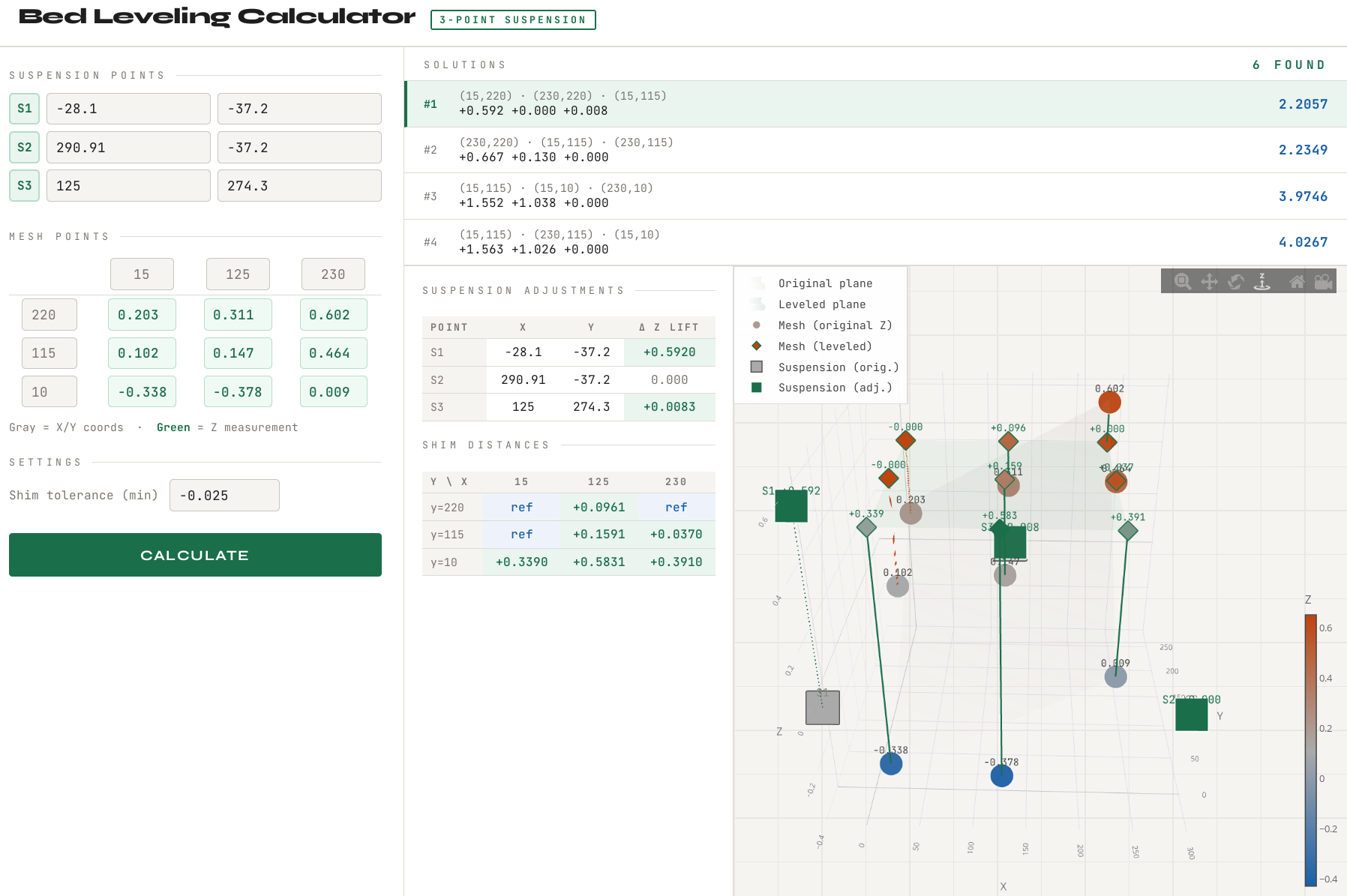
$ python parse-bedmesh.py
MESH_Z = [
  # x=15    x=125   x=230   (for each y row)
   0.203,   0.311,   0.602,  # y=220
   0.102,   0.147,   0.464,  # y=115
  -0.338,  -0.378,   0.009,  # y=10
].freeze
And then you either plop this into the bed-leveling-calculator.rb and get textual output, or you manually enter the values into the bed-leveling-calculator.html (that you download and open in your browser), which would give you the interactive page with the possible solutions and visualization...
RE:
Btw, it is all described in the blog post ( https://wejn.org/2026/03/leveling-prusa-core-one-bed/ ) but I'll freely admit that it's very... wordy. Because I tried to capture it from the "I know next to nothing about any of this" standpoint, to make it more useful for total beginners (and me in 6 months).
RE:
Ah, I was hoping I could just copy/paste from the serial output into bedviz.html
I'll look into it at the weekend and see if thats something I can implement easily.
It's very useful to just probe the standoffs though, as basically thats the only parts we can shim/adjust. 👍
When I get my head around it, I'll implement your approach into my ESP Monitor. I was never happy with the approach I was using, this appears much better.
RE: OctoPrint bed visualizer gcode
For standoffs, you run the probe-standoffs.gcode which probes the standoffs and dumps each measurement into a file.
If you use the run_gcode.py, that is. That's why some of the lines are prefixed with a star (*), to tell that script to save the output as an individual file.
RE: OctoPrint bed visualizer gcode
Ah, I was hoping I could just copy/paste from the serial output into bedviz.html
Oh you absolutely can. Just run each gcode in sequence, and fill out each gathered value into the bed-leveling-calculator.html. That should be very doable, even if a tad more manual.
RE:
E.g.
>> G29 P10 V4 X15 Y10
<< echo:probe: enabling high-precision in single-probe mode
<< echo:Re-tared with offset 1.86
<< echo:Starting probe at 1
<< echo:busy: processing
<< echo:Probe classified as clean and OK
<< Bed X: 15.000 Y: 10.000 Z: 0.038
<< ok
gets you the 0.038 Z offset for X=15 Y=10 for the bed leveling calc page (lower left corner, where it says -0.338 on the picture):
RE: OctoPrint bed visualizer gcode
OK so I've got the 'Wejn' method now working on my ESP monitor👍
Claude did the heavy lifting, I was on the sidelines cheering him on 😂
RE: OctoPrint bed visualizer gcode
I've been thinking of porting over the mesh visualization tools from OctoPrint to PrusaSlicer as my next project. It wouldn't be too hard and yes Claude AI is doing all the work however... The imminent (or not) release of the semi-mythical PrusaSlicer 3.0 has me pausing on any new activity.
RE: OctoPrint bed visualizer gcode
Yeah I can see exactly why you'd pause now wrt the calibrations.
I doubt they'd ever introduce mesh topology to the public though...it highlights exactly how skewed and out of tolerance a lot of their parts actually are 😂
If you're going to include mesh stuff, especially for the C1, use the approach that Wejn has used here...ie, just probing the expansion joints.