RE: Nozzle cleaning consistently fails with PETG
I've been lurking around this thread also as I await my eventual conversion kit. I'm curious to know if anyone else had previously looked at their load cell output, or even better, compared it with the readings seen when tapping on the nozzle if a fully functional Mk4(s)? With one report of a connection, it seems a great place to start. It would be incredible if it's as simple as a more careful assembly, or in a worse case, Prusa might be able to spec this part with a bit longer wire bundle on future parts (if I'm understanding the description above correctly).
Hopefully others who are experiencing this can do similar testing and confirm or challenge this theory.
-J
RE: Nozzle cleaning consistently fails with PETG
Hi there,
I also faced this issue a lot. Almost every print needed babysitting to pass the nozzle cleaning step, even though it was shining clean as brand new...
I made several assumptions, especially like some other found here that using an old MK4S satin sheet for instance may lead to inconsistent measurement because of the marking. But even when I pull down the plate off of 20mm in Y, I had a lot of failure. I also attempted a manual calibration using the good old business card grabbing technique. I may have found it was possibly better with PLA without certainty, but I still had failures with PETG, ASA, PC-ABS and most of all, even without any filament loaded...
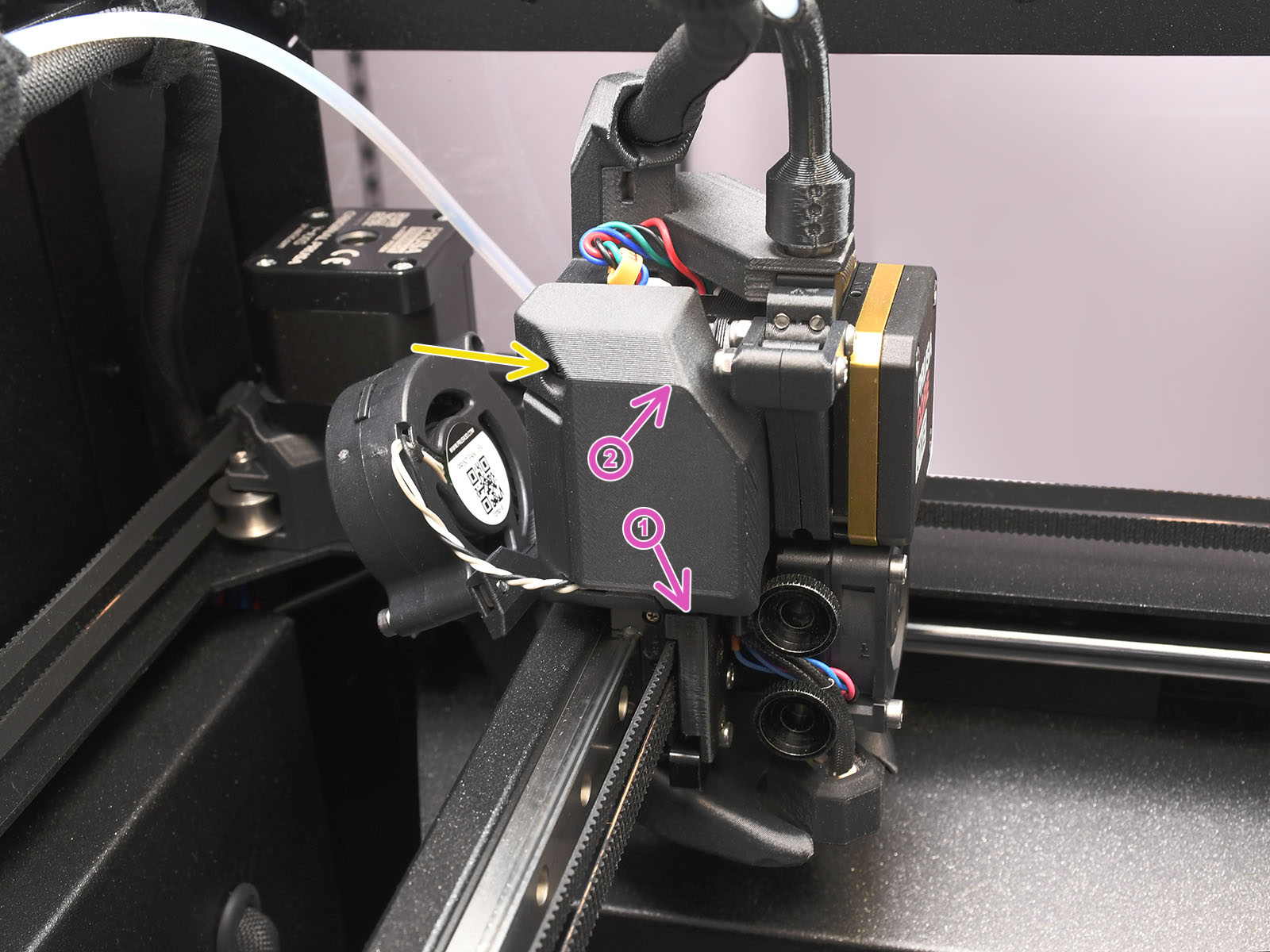
Then I took the time to look at this CORE One and using the Sensor Info menu to look at the loadcell value, I almost immediately understood what was going on. The loadcell is over-constrained by the pneufit mount plus the cable bundle relief. I first unmounted the pneufit but it wasn't enough, very visible on the value of the loadcell. Then I released a bit the two screws of the mount/cover at the back of the nextruder and... 100% success on 12 attempts in a row mixing PETG and PC-ABS!
Try by yourself, touching "normally" the nozzle produce a variation of ~300 of the sensor value, but a slight touch on the cable bundle can produce hundred to thousand points of delta, and the value may even not go back to ~0.
Next step when I'll find time is to take down the nextruder assembly and re-mount it appropriately, if possible, hoping the defect keep away from my printer.
I checked mine. Similarly I see about 300 count difference when pressing the nozzle with my finger but if I deflect the wiring harness about +/-1/2" I still only see about +/- 300 counts. I haven't had any issue with the nozzle cleaning.
RE: Nozzle cleaning consistently fails with PETG
The loadcell is... the whole complex aluminum part of the Nextruder. It is sensitive enough to detect a finger press anywhere on the printhead (without locating it of course).
Ah, I see -- thank you. Also found the Nextruder assembly instructions in the MK4S kit manual now.
So the loadcell sensor can detect strain within that aluminum part. But shouldn't its upper part (the L-shaped mounting bracket) be firmly mounted to the carriage on the X gantry, and forces on the lower part (with the bore for the hotend and the fan grille) get sensed? Any forces from cables tugging at the upper end should not deform the aluminum part as long as its bottom end is suspended freely, I would expect.
Is it possible that anything tugs at the lower end of the Nextruder/loadcell assembly? E.g. the heater cables running up along the side, wedged in between those knurled screws, look a bit suspect to me.
RE:
The loadcell is... the whole complex aluminum part of the Nextruder. It is sensitive enough to detect a finger press anywhere on the printhead (without locating it of course).
I hope to be right, and I hope this could be confirmed by someone else in the meanwhile.
I am very interested in where you got this picture. The style of the arrows reminds me a lot of the instructions from Prusi for assembling the CoreOne kit. I am also convinced of this by the fact that you do not mention the meaning of the arrows anywhere (which you would certainly do if you were the author of the arrows), and in the original context they definitely have a different meaning. And the official Prusi website does not present the assembly instructions anywhere.
RE: Nozzle cleaning consistently fails with PETG
Ah, I see -- thank you. Also found the Nextruder assembly instructions in the MK4S kit manual now.
So the loadcell sensor can detect strain within that aluminum part. But shouldn't its upper part (the L-shaped mounting bracket) be firmly mounted to the carriage on the X gantry, and forces on the lower part (with the bore for the hotend and the fan grille) get sensed? Any forces from cables tugging at the upper end should not deform the aluminum part as long as its bottom end is suspended freely, I would expect.
Is it possible that anything tugs at the lower end of the Nextruder/loadcell assembly? E.g. the heater cables running up along the side, wedged in between those knurled screws, look a bit suspect to me.
Hang on... Having looked at the Core One picture again, and read further down in the MK4S instructions -- is it the lower part of the Nextruder assembly which gets bolted to the X carriage?! I.e. the very part which holds the hotend?
If that is case, I must be misunderstanding the idea of the loadcell entirely. How can it detect touches to the hotend (via flex/strain of that complex aluminum part) if the hotend-holding section is bolted down? The loadcell looks more like a sensor designed for detecting strain on the upper section of the aluminum part then?!
That can't be right. Could somebody please help me out and explain where I misunderstood the design?
RE: Nozzle cleaning consistently fails with PETG
If I look closely at the structure of the aluminum part, only its rear part is firmly attached to the X carriage. The side where the nozzle is inserted and fixed is connected to this part only by ribs for the passage of air from the fan. And these ribs are thin and flexible enough that their deflection and the resulting mechanical stress can be evaluated by the strain gauge in the LoadCell and converted into a corresponding change in the output voltage, which the AD converter in the processor can evaluate. It is necessary to realize that the deflection of the flexible ribs will be in the order of tenths and maybe hundredths or even thousandths of a micron. I cannot estimate the size of this value. That's my opinion on the matter.
RE: Nozzle cleaning consistently fails with PETG
I'm curious to know if anyone else had previously looked at their load cell output, or even better, compared it with the readings seen when tapping on the nozzle if a fully functional Mk4(s)?
I did this comparison with my MK4S and my XL. The MK4S simply don't have anything mounted at the top of the heatsink, so it is far less impacted. But the XL also have a lot of variation on the loadcell output when jiggling the cable mount. It reminds me a similar issue at the beginning of the XL, maybe it is fixable by adjusting some threshold in the firmware.
the official Prusi website does not present the assembly instructions anywhere.
There are already a bunch of assembled CORE One in the nature, so they need maintenance and troubleshooting. 😉
https://help.prusa3d.com/manual/printer-maintenance_247/core-one
https://help.prusa3d.com/product/core-one/troubleshooting_194
That can't be right. Could somebody please help me out and explain where I misunderstood the design?
In the absence of assembly manual, I couldn't be sure until I teardown the printhead.
RE: Nozzle cleaning consistently fails with PETG
If I look closely at the structure of the aluminum part, only its rear part is firmly attached to the X carriage. The side where the nozzle is inserted and fixed is connected to this part only by ribs for the passage of air from the fan. And these ribs are thin and flexible enough that their deflection and the resulting mechanical stress can be evaluated by the strain gauge in the LoadCell and converted into a corresponding change in the output voltage, which the AD converter in the processor can evaluate. It is necessary to realize that the deflection of the flexible ribs will be in the order of tenths and maybe hundredths or even thousandths of a micron. I cannot estimate the size of this value. That's my opinion on the matter.
Ah, right -- the aluminum part is bolted down on its right-hand side and in the center (looking at it from the front of the printer), and the left-hand side which holds the hotend can flex up and down a bit. But given the placement of the load cell (strain gauge), I am not surprised that it is also sensitive to stresses induced via the upper end of the aluminum piece.
Wouldn't it have been better to either decouple (separate) that upper part completely from the lower aluminum part which carries the load cell? Or make the upper part very stiff by designing it as a closed frame, rather than the open L shape it has now. As currently designed, it looks like a pretty sensitive coupler to guide strains from the cables or PTFE tube towards the load cell.
RE: Nozzle cleaning consistently fails with PETG
What I can perhaps contribute to the topic is the following. I also had the problem that the cleaning failed pretty much every time I printed PETG. And I also always had this pancake of gunk around the nozzle (and yes my PETG is moist). But then my stock 0.4 nozzle had that bad clogg with PLA. I was forced to switch to a E3D Obxidian HF 0.6 nozzle. Same PETG (different Profiles due to different diameter) no problems, also no gunk arround the nozzle. In the meantime i switched back to a 0.4 brass nozzle, but not the one that was installed. I opted for the E3D brass HF 0.4 and only had one failed cleaning (same profiles, same wet petg, no cleaning of the nozzle by hand before printing). To be fair i had one failure but it was obvious due to a piece of filament sticking to the nozzle.
RE: Nozzle cleaning consistently fails with PETG
Wouldn't it have been better to either decouple (separate) that upper part completely from the lower aluminum part which carries the load cell? Or make the upper part very stiff by designing it as a closed frame, rather than the open L shape it has now. As currently designed, it looks like a pretty sensitive coupler to guide strains from the cables or PTFE tube towards the load cell.
Unfortunately, your proposal is not feasible. The extruder idler mechanism is housed in that L-shaped cutout. And if you were to split the structure into two parts, it would be difficult to keep them exactly aligned with the nozzle axis, and it would be difficult to mount the upper part on the X-carriage because the entire surface would be covered by the extruder motor and gearbox.
RE: Nozzle cleaning consistently fails with PETG
Unfortunately, your proposal is not feasible. The extruder idler mechanism is housed in that L-shaped cutout.
Make the aluminum part a mm thicker, or the idler a mm slimmer in that region, to allow for a connecting strut which "closes the loop" on the upper part of the aluminum piece?
RE: Nozzle cleaning consistently fails with PETG
What I can perhaps contribute to the topic is the following. I also had the problem that the cleaning failed pretty much every time I printed PETG. And I also always had this pancake of gunk around the nozzle (and yes my PETG is moist). But then my stock 0.4 nozzle had that bad clogg with PLA. I was forced to switch to a E3D Obxidian HF 0.6 nozzle. Same PETG (different Profiles due to different diameter) no problems, also no gunk arround the nozzle. In the meantime i switched back to a 0.4 brass nozzle, but not the one that was installed. I opted for the E3D brass HF 0.4 and only had one failed cleaning (same profiles, same wet petg, no cleaning of the nozzle by hand before printing). To be fair i had one failure but it was obvious due to a piece of filament sticking to the nozzle.
That's interesting. I had no issues with nozzle cleaning but I was also switching nozzles from the beginning. Maybe just loosing the thumb screws, releasing tension in cables and tightening it again may solve these nozzle cleaning issues? Can you guys try it and confirm if it helps?
RE:
Can you guys try it and confirm if it helps?
I am currently trying hard. Top panel removed (to feed filament without using the PTFE), side filament sensor disabled, PTFE+pneufit removed, two back screws released, I am still confirming that it solves the issue for me. So far so good excepted only for one fail with PETG, but the nozzle wasn't clean indeed and I cannot ensure that the influence from the cable is fully removed by just releasing (without fully remove) those screws without taking apart more parts of the assembly.
In the next days I'll revert all and confirm that the issue is back (or not), and only then I'll teardown the printhead to find a way to relax the strain on the loadcell. But not before the weekend...
But looking at the printhead from the outside, the only big difference with a MK4S/MMU3/XL is the cable fastening.
RE: Nozzle cleaning consistently fails with PETG
I did open a GitHub issue 2 weeks ago, but it seems that at least for CF material the solution is quite simple: Increase the retraction from -1 to -3 in the end code. I am testing it right now, but it did the trick on the last two prints.
RE: Nozzle cleaning consistently fails with PETG
In the next days I'll revert all and confirm that the issue is back
On my side, rebolting back the whole printhead made the issue to come back. Two prints, two fail.
I did a simple test, auto-home followed by a move X to the left. At the auto-home position the loadcell value is zeroed (tare), at X=10mm the loadcell value increased up to +300, which is equivalent to a finger press on the nozzle.
This weekend I'll try to find the time to disassemble the printhead and to find a way to release the strain of the cable bundle over the loadcell.
For information, the print fan that is bolted directly onto the machined X carriage, with no interaction with the loadcell at all. If I press/pull this fan, I can see a variation of +/-50 on the loadcell output. I doubt that it can deform the machined carriage, but it can maybe very slightly move the MGN carriage in rotation around the X axis. Then this variation can probably only come from an external reference: the cables and the PTFE tube.
RE: Nozzle cleaning consistently fails with PETG
The solution with an additional 2 mm retraction is not bad, but not perfect either. I had a lot less nozzle cleaning aka z offset verification errors, but not none. This is ASA CF/PCCF, so your milage may vary. With pure ABS, even with standard settings, it had 4/5 successes. CF materials are my issue.
RE: Nozzle cleaning consistently fails with PETG and PC-CF
Good fellow Core One Beta testers, I can confirm that I have nearly perfect nozzle cleaning with PLA with the same 0.4 ObX HF nozzle that constantly fails with PC-CF. Of course the difference is both filament stiffness and temperature, both are Prusa filaments dried before and during printing. Hopefully this is sorted out soon.
RE: Nozzle cleaning consistently fails with PETG
I'm completely new to 3D-printing and I also have this problem. In addition to the roll of PLA that came with the printer, I bought two rolls of PETG. I've only been able to make a couple of prints with PETG, because the nozzle cleaning keeps failing. First I wondered whether the problem was because I used PETG on the steel sheet (yes, I ruined one side of the sheet learning PETG doesn't go on steel), so I purchased a satin sheet hoping it would solve it. But no. PETG still fails at nozzle cleaning.
I had to switch back to the PLA roll to get anything done.
RE: Nozzle cleaning consistently fails with PETG
Hello.
Happened to me also.
Lower the 170ºC temp to 150ºC in these two places

RE: Nozzle cleaning consistently fails with PETG
This problem should be largely fixed with the newly released Firmware 6.3.1
Automatic filament retraction
We’ve introduced automatic filament retraction at the end of a print, with reinsertion just before the first extrusion. This brings several benefits:No filament remains in the nozzle during mesh bed leveling, helping prevent filament specs from being left on the print bed.The nozzle no longer needs to be heated for filament unload.
Note: This is a pilot implementation of the procedure. If it proves effective, we plan to extend it to other printers as well.
Note: Auto-retraction is not performed for flexible filaments. To support this, we’ve added an "Is flexible" parameter for filaments, configurable via the GUI (for user presets) or using the M865 G-code.
I've just flashed it, and it also applies directly after a filament change, so there is never filament in the nozzle until the print is actually printing