Squaring the Gantry - Going Crazy
Hey there - newbie here (previously a resin guy before the Core ONE) and I'm pulling out my hair over this. Hoping the collective wisdom of the community can point me in the right direction.
Context:
When calibrating belts at the end of assembly, both were very loose. There was a little bit of lack of square in the gantry that I was trying to sort out and I started tuning the belts (they were very loose). The y-axis belt slipped out of the nextruder assembly mount on the gantry. Had to leave it like this for a few days as life got in the way.
I unmounted the nextruder and got at the nextruder mount on the gantry. Reattached the belt (did 5 instead of 4 teeth this time). Everything seems relatively seated well and like it wont slip out again.
However, now there's even more of a gap between the gantry and the end. The picture below shows where the X belt side is when the Y belt side is pulled all the way to the front.
In addition, trying to tighten the belts to 85 hz seems almost impossible. The Y side (the side that slipped) is constantly 110-140 or so and the X side is barely flopping around. When I tighten the X side the Y side gets even tighter and when I loosen it up the Y tensioner slips off the screw.
Question:
So I think there's two problems, and I'm not sure if they're both important to solve:
1) This seems like a rather big gap... And tensioning the belts doesn't seem to change it. If I do somehow get the belts at equivalent tensions
2) The belt tension difference seems massive... And I can't seem to get the Y belt to loosen up anymore without it coming unscrewed.
Any advice?
Pictures:
Space it has now:

Space it had before the belt slip (if helpful):

Best Answer by TheBrohirrim:
I have resolved the cause here with the stellar help of Andres from support. I thought I might have had a bent gantry or something else. But I believe I found a novel way to mess up, so I'm documenting it.
This is what was borked: https://help.prusa3d.com/guide/5-corexy-assembly_835522#844219
There are three screws at this part, but four holes. I had the orientation of the XY-Carriages attached to the Linear Holder rotated by 180 degrees, which will still be screw-in-able because there are four holes. The cutaway/silloutte of the top of the XY-Carriage should match the metal parts around it.
A few signs this is your issue:
- The Gantry is squared when the belts aren't connected, but gets unsquared when you attach belts to tensionser pullys
- One of the belts is extremely tight. Before running them through the nextruder mount, they should overlap at least an inch
- You have to undo tensioners to run the belts OR one of the belts is extremely tight compared to the other. They're both ~5 foot on the dot and should have the exact same slack.
- The belts don't look exactly like the image from this step: https://help.prusa3d.com/guide/5-corexy-assembly_835522#845821 (mine were running like the image below, where teal shows where the pink line was off)


Remediation was simple.
This piece can easily be unscrewed and flipped 180 degrees and reattached. It will require you to re-run belts through the flipped part, but you should be able to avoid having to re-run the entire belt.
To get at the belt, if you're finding this during the calibration stage (as I did) you will have to remove the nextruder assembly to remove the nextruder holder on the belt.
This can likely be discovered during the initial belt run step by QCing that the belt paths match exactly as well as checking the silloutes of the XY Carriage assembly against the metal piece.
RE:
No answers yet, so I'll chip in with the observation that the gap looks enormous. Sounds like you need to go back a few steps in the assembly as the adjustments you're making now are more for fine adjustment of the belts rather than what you have there. My Core One was already assembled, so take my advice with that in mind.
RE: Squaring the Gantry - Going Crazy
When I build mine as full kit I got the belt ends all the same on the gantry bracket so i looked like pic in the build manual. With both belts very loose one side was not hitting the stop when held either side like 2mm out of square so with gantry away from stop hold good side and gently pull forward the bad side after a couple goes it squared up and holding either side it would hit both stops, then do belt tension and got within 1hz of each other tried before and couldn't get any better than about 10hz when it wasn't hitting both stops evenly.
RE: Squaring the Gantry - Going Crazy
Agree with @SteveH - that gap looks way bigger than it should be. I assembled my printer from a kit and after assembly my gap was probably around a mm or less and only need some light tuning. I would backtrack a little - check the gantry is square also.....
RE: Squaring the Gantry - Going Crazy
Agree with @chris77-2, you should first make sure that the gantry is orthogonal to the Y axes before you tension the belts. The brackets which connect the gantry to the Y bearing blocks are likely culprits: Coming from the factory, they don't necessarily have 90° angles.
Given the large deviation in your build, I would go one step beyond Chris' advice and suggest that you check (and correct if necessary) the brackets individually:
- Fully loosen the belts.
- Disconnect the bracket from the gantry on one side; then gently bend the gantry (and hence the bracket which is still attached to it) to be at 90° to the Y rods.
- Re-attach the bracket, disconnect the opposite one, square the gantry again.
- Re-attach the other bracket.
Now the gantry should be squared with the Y rods, and both brackets should agree (i.e. not be under tension, working against each other). Gradually tighten both belts, alternating between the belts, and see whether you can arrive at a symmetrical setup -- with equal belt tensions and square gantry.
RE: Squaring the Gantry - Going Crazy
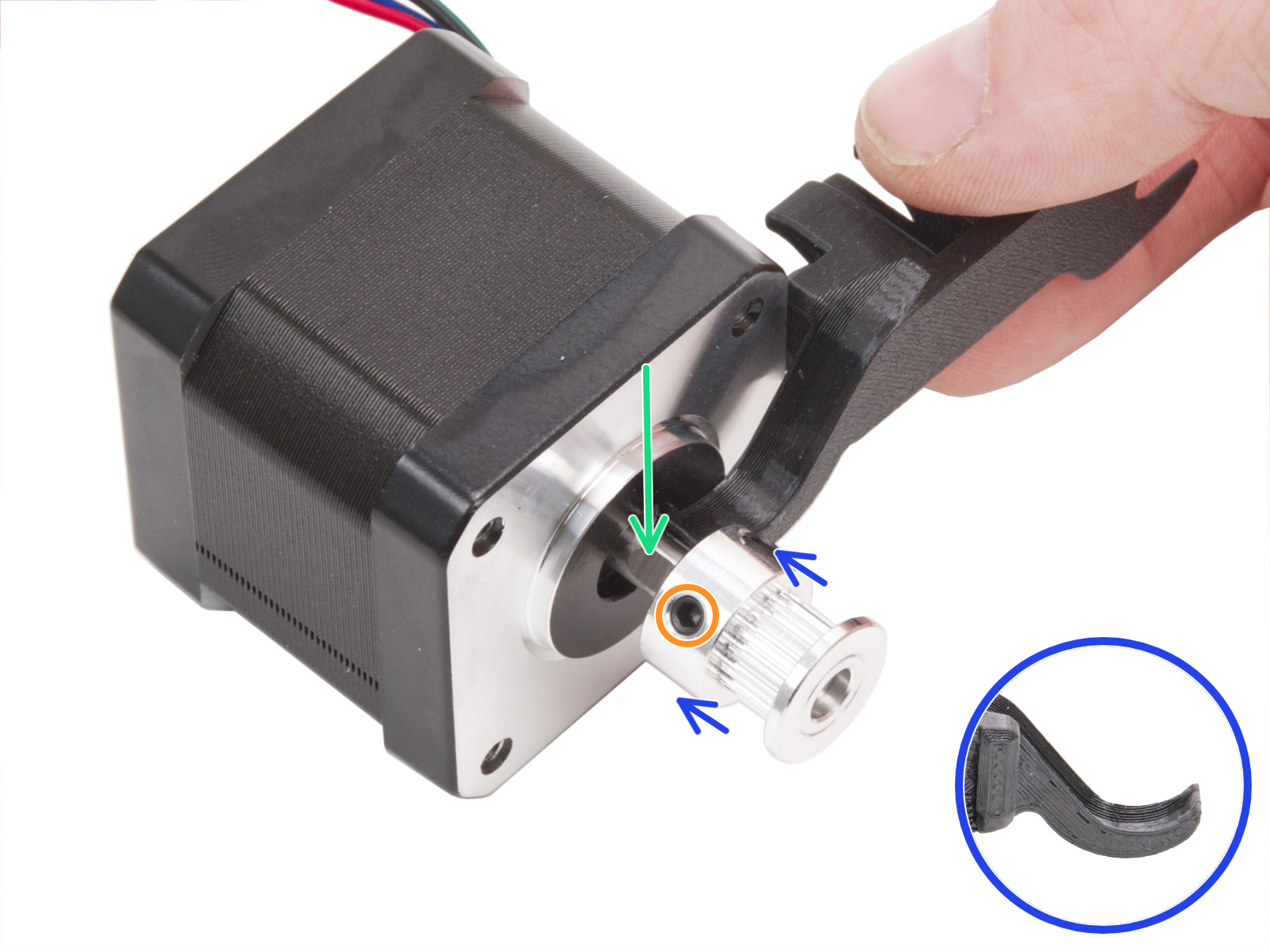
Have you verified the pulley installation is correct on the x- and y-axis motors? There's been several people who have installed one (or both) upside-down. They need to be oriented very specifically as shown in the assembly guide:
https://help.prusa3d.com/guide/5-corexy-assembly_835522#843284
x-axis:
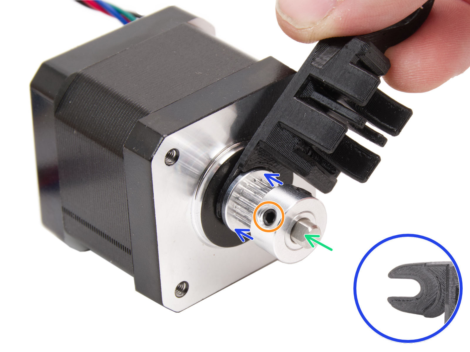
y-axis:
RE: Squaring the Gantry - Going Crazy
Have you verified the pulley installation is correct on the x- and y-axis motors? There's been several people who have installed one (or both) upside-down. They need to be oriented very specifically as shown in the assembly guide:
https://help.prusa3d.com/guide/5-corexy-assembly_835522#843284
x-axis:
y-axis:
Me! Thank you for this!
"Just" the x pulley was backwards. I was very careful doing that. The gap to the motor was perfect.🙄
Very frustrating, but I guess that's one of the things the test is good for.
I pulled the side panels off, pulled out the motor bolts, put a wrench though the belt while juggling the motor and pulley. Worst part was fighting the nylon rivets.
By the time I figured this out, my gantry was straight and belt tuning was pretty easy.
RE: Squaring the Gantry - Going Crazy
I have resolved the cause here with the stellar help of Andres from support. I thought I might have had a bent gantry or something else. But I believe I found a novel way to mess up, so I'm documenting it.
This is what was borked: https://help.prusa3d.com/guide/5-corexy-assembly_835522#844219
There are three screws at this part, but four holes. I had the orientation of the XY-Carriages attached to the Linear Holder rotated by 180 degrees, which will still be screw-in-able because there are four holes. The cutaway/silloutte of the top of the XY-Carriage should match the metal parts around it.
A few signs this is your issue:
- The Gantry is squared when the belts aren't connected, but gets unsquared when you attach belts to tensionser pullys
- One of the belts is extremely tight. Before running them through the nextruder mount, they should overlap at least an inch
- You have to undo tensioners to run the belts OR one of the belts is extremely tight compared to the other. They're both ~5 foot on the dot and should have the exact same slack.
- The belts don't look exactly like the image from this step: https://help.prusa3d.com/guide/5-corexy-assembly_835522#845821 (mine were running like the image below, where teal shows where the pink line was off)
Remediation was simple.
This piece can easily be unscrewed and flipped 180 degrees and reattached. It will require you to re-run belts through the flipped part, but you should be able to avoid having to re-run the entire belt.
To get at the belt, if you're finding this during the calibration stage (as I did) you will have to remove the nextruder assembly to remove the nextruder holder on the belt.
This can likely be discovered during the initial belt run step by QCing that the belt paths match exactly as well as checking the silloutes of the XY Carriage assembly against the metal piece.
RE: Squaring the Gantry - Going Crazy
Thanks for posting the solution.
Have a nice day!