RE:
I agree with bryn51, the LM317 is likely not a good choice. The issue is that you're converting 24v down to 5v with a linear regulator. Linear regulators "burn off" voltage by converting it to heat. Terrible way to describe it, but easy enough to say. How much heat?
You're dropping from 24v down to 5v, so a 19v drop. I'm not sure how much current is used on the 5v rail, but it looks like it is mainly a microcontroller and some LEDs. I think 100mA of average current is a fair estimate. 19v * 100mA = 1.9 watts. I pulled up the LM317 datasheet from ST Micro and the best package for thermal dissipation is the TO-220. It has a 50°C per watt temperature rise. Since power dissipation is calculated at 1.9 watts, that's 50°C/watt * 1.9 watts = 95°C above ambient. I have my printer in an enclosure, and the temperature at the MMU is 33°C. So, expected temperature of an LM317 is 95°C + 33°C = 128°C.
128°C is worst case, if you use a TO-220 package and my 100mA estimate is decent. You can improve that by adding heat sinking or air flow, but that doesn't really make the choice any better. You're still dumping that heat into the MMU (if you put the regulator in there) and that's enough to soften the plastic, possibly warp it.
If I go to Amazon and search for "buck regulator" or "buck converter" I get a lot of options. I don't know the proper French translation for that, or really anything if I'm being honest. You can also try searching for "LM2596" as that is what many of the cheaper, but perfectly capable, buck regulators are made with. Heat dissipated by this type of regulator (switching regulator) is typically far superior in terms of power dissipation to an LM317 (linear regulator) when large voltage drops and non-trivial currents are involved.
All that said, I think the argument that the 5v rail is too low is bogus. I'm totally on board with bryn's thinking that this is oxidation on the connector terminals. To test this, just power off the printer and then unplug and replug all of the connectors on the MMU half a dozen times and see if that fixes it.
RE: I found serious design error in MMU2 electronics hardware
Follow up: Despite me being aligned with bryn regarding what is causing the actual issue, I did remove the diode that others have referred to in order to increase my 5v rail. I think it was D1.
https://github.com/prusa3d/MM-control-2.0/blob/master/rev.03/MM-control.pdf
RE:
You really don't want a linear regulator like the LM317, as you have to feed it with 24v*.1A or nearly 2.5 watts. Switching regulators can be about 80% efficient.. So if you estimate 100mA @5v you are looking at 0.5watt out and .5/2.5 or about 20% efficiency for the 317. .. If your switching regulator is 80% efficient you only draw about .7 watts from the power supply or .7/24 or about 30mA, rather than 100ma.. How well it works depends how much overhead you have to draw from your power supply.. I'd be really surprised if all these problems were due to oxidation of the connectors.. The MK3+ is drawing amps through those connectors and there is no issue there. 100ma draw does not create much potential drop across the terminals.. Those crimps would have to be really bad.
2 watts can generate surprising heat and you'd need a decent heatsink with thermal grease on the TO 220 and mount it somewhere the heat can escape the heatsink.
RE: I found serious design error in MMU2 electronics hardware
I thought I posted an example of a very inexpensive switching regulator earlier in this thread.
Here it is again if that was another thread.
There are all kinds of variations on this theme, and items like this are available almost everywhere. Amazon has countless options.
I like this one in particular because it has a built-in meter for no-muss no-fuss adjustment.

RE: I found serious design error in MMU2 electronics hardware
I'd be really surprised if all these problems were due to oxidation of the connectors.. The MK3+ is drawing amps through those connectors and there is no issue there. 100ma draw does not create much potential drop across the terminals.. Those crimps would have to be really bad.
The corrosion issue isn't really with the 100mA draw of the 5v pin, it is corrosion on the motor phase pins that is suspected.
I don't think that the issue is with the slightly low voltage on the 5v rail. Someone saw the roughly 4.2v on a multimeter and saw that in the datasheet the rail is supposed to be a 4.35v or something like that. I don't recall the exact numbers. Yes, I agree that the 5v rail is too low (which is why I went ahead and fixed mine) but no, that isn't the problem that leads to the flashing LEDs. What will an out of spec voltage rail do to a microcontroller? Probably make it crash and run off in to the weeds if anything.
When a micro is off in the weeds, it does all kinds of random crap. It does NOT blink LEDs in a controlled manner like what we're experiencing here.
So how can the MMU blink all of the LEDs? It does that when it detects an error that it cannot recover from. In order to detect a hardware error that it cannot recover from, the firmware must be running properly. It reads the data from the motor drivers and checks flags for errors. If it sees a flag is set, it clears it and tries again. When it has tried and failed to recover, it starts blinking the LEDs.
What causes motor errors? Well, when the motor doesn't do what the motor driver tells it to do. What can cause that? Either the motor is jammed (like a filament is stuck in the MMU selector while it is trying to move) or there is corrosion on the pins so the motor is starved for current, which lowers torque, which leads to missed steps.
That's why I don't think this is a 5v problem at all. The microcontroller operates far too reliably for far too long for far too many people before they experience this type of issue.
RE: I found serious design error in MMU2 electronics hardware
If anyone else wants to follow up and review the same information I looked at...
Microcontroller data sheet - http://ww1.microchip.com/downloads/en/DeviceDoc/doc2503.pdf - List of interrupt vectors is on page 44. I don't see an interrupt vector for a general exception (such as a divide by zero, or null pointer address, etc).
My previous post on reviewing the firmware - https://forum.prusa3d.com/forum/postid/625725/ - I point out how the firmware gets to the led-blinky-state
MMU schematic - https://github.com/prusa3d/MM-control-2.0/blob/master/rev.03/MM-control.pdf
MMU firmware source - https://github.com/prusa3d/MM-control-01
RE: I found serious design error in MMU2 electronics hardware
And yet when the 5v input is fixed the problem is entirely resolved, and nothing was done to any of the other connectors. All three of mine have never had the problem since I fixed the 5v input.
RE: I found serious design error in MMU2 electronics hardware
Thank you all very much!
Thank you for all your precise and clear explanations !
I love your answer about temperature, power loss, orders of magnitude and all the consequences that follow.
So I'll buy (on aliexpress) a LM-2596 (with or without Volt display).
I have a buck DC/DC converter as a power supply and the manual PROHIBITS connecting an input to an output at the risk of destroying the power supply, even between the (-) minus poles.
My question (for mmu2s) : Can I connect the 2 (-) minus poles together on this buck converter LM-2596? or what should I do?
Once again: Thank you very much for your answers! Have a nice day!
F. (from France)
RE: I found serious design error in MMU2 electronics hardware
I don't have an MMU, but being in Electronics, just by the observational data reported here.. it appears that having a 5v rail after the diode fixes some significant issues for people. I haven't looked into the electronic design in detail.. but maybe just the higher voltage allows more current to the motors and more torque.. But something in there is very marginal on 4.3 volts, in my very quick and not fully informed assessment. So some work.. and some don't.. It is certainly something that Prusa should look into for reliability and customer happiness. But purely a guess.. I have no unit that would allow me to measure the electrical parameters inside.
And yet when the 5v input is fixed the problem is entirely resolved, and nothing was done to any of the other connectors. All three of mine have never had the problem since I fixed the 5v input.
RE: I found serious design error in MMU2 electronics hardware
I don't have an MMU, but being in Electronics, just by the observational data reported here.. it appears that having a 5v rail after the diode fixes some significant issues for people. I haven't looked into the electronic design in detail.. but maybe just the higher voltage allows more current to the motors and more torque.. But something in there is very marginal on 4.3 volts, in my very quick and not fully informed assessment. So some work.. and some don't.. It is certainly something that Prusa should look into for reliability and customer happiness. But purely a guess.. I have no unit that would allow me to measure the electrical parameters inside.
And yet when the 5v input is fixed the problem is entirely resolved, and nothing was done to any of the other connectors. All three of mine have never had the problem since I fixed the 5v input.
I have an electronics background, working in electronics design and repair since the mid 80's. It is my opinion that if the microsopic about of corrosion that is being discussed by the Deoxit proponents is responsible for the problems, then that is simply symptomatic relief, because if such a small voltage drop through the connector is causing these problems, then the tolerance designed into the entire circuit was vastly insufficient.
It's a bad design to which deoxit is applying a band-aid. Fixing the 5v rail, demonstrates that the problem is with the design.
A better design would have been to simply incorporate a 24v to 5v BUC into the MMU2S board. After all there is BOTH a 24v and a 5v supply to the MMU2S board from the Einsy board.
RE: I found serious design error in MMU2 electronics hardware
And yet when the 5v input is fixed the problem is entirely resolved, and nothing was done to any of the other connectors. All three of mine have never had the problem since I fixed the 5v input.
That isn't entirely correct. Most people will be handling their printer when they're doing mods like this. If you open the MMU, you've affected those connectors (you can't flip the top back without stressing those cables). Just wiggling the cables on the back of the MMU may clear off some of the fretting corrosion. That stuff is super soft and super easy to clean off. Ever had to unplug something and plug it back in and it worked? You might have had some fretting corrosion.
Did you open the MMU to verify that the 5v rail was at or near 5v and not 4.2v any longer? Or maybe you put the regulator's output directly to the 5v rail and skipped the diode. If either of those are true, then yes, you had to open the MMU, put stress and significant movement on the motor connectors, and then that could clear the corrosion. Easily.
I see in your post history that you did put the regulator inside of the MMU. This issue doesn't occur quickly. It can take a long time for fretting corrosion to build up. I had mine for more than a year before it acted up.
I have a buck DC/DC converter as a power supply and the manual PROHIBITS connecting an input to an output at the risk of destroying the power supply, even between the (-) minus poles.
My question (for mmu2s) : Can I connect the 2 (-) minus poles together on this buck converter LM-2596? or what should I do?
Can you post the manual where it prohibits it? Perhaps there is a misunderstanding. If it is in French, I won't be able to help (probably). But generally, yes, you want to
- Power down the printer
- Connect the ground (-) of the buck regulator to the ground of the MMU/printer.
- Connect 24v from the printer to the buck regulators input.
- Power up the printer
- Adjust the buck regulator to output 5.5v or so
- Power down the printer
- Disconnect 5v from the MMU
- Connect the regulator's 5v output to the MMU
- Power it back up
Posted by: @fissi0n
I have an electronics background, working in electronics design and repair since the mid 80's. It is my opinion that if the microsopic about of corrosion that is being discussed by the Deoxit proponents is responsible for the problems, then that is simply symptomatic relief, because if such a small voltage drop through the connector is causing these problems, then the tolerance designed into the entire circuit was vastly insufficient.
I have 20+ years of experience in embedded system design and programming those designs. I think we both have valuable information to share.
Fretting corrosion builds, and builds, and builds, and builds as the tin oxide on a tin surface is rubbed by another object. The MMU is mounted on top of a vibrating platform and uses tin connectors with gold crimps in the motor's cables (I might have that backwards). When the crimp (gold or tin, doesn't matter) rubs against the surface of the connector pin, it will cut through the very soft (and very electrically insulating) tin oxide. The tin oxide builds up in a mound, and eventually the crimp pin rides up the mound and loses contact with the pin below. This isn't a "slightly resistive" connection now, it is now an open circuit. Open circuits cause the motors to miss steps.
The motor drivers used in the MMU can report issues, such as missed steps. The firmware checks for errors, and when it finds them, it enters an error routine. That error routine is to blink the lights.
The firmware does NOT check for a low 5v rail. It does NOT enter the blinking LED routine when the 5v rail is low because it is NOT looking at the voltage on that rail. I seriously doubt the microcontroller will always end up in the blink-the-leds-routine when it crashes. It just doesn't make any sense for a glitch on the 5v rail to send it to the error routine. Maybe it would restart, or go off in the weeds, or the motors would start doing sketchy things.... but going into an error routine to report motor errors when there's a 5v problem? I just don't buy it.
Here's a short video that shows a little graphic on it. It doesn't go into much detail, but it might help to visualize the issue:
RE: I found serious design error in MMU2 electronics hardware
And yet, after fixing the 5v rail, and doing NOTHING ELSE, the problem is fixed on all three MMU2's that I own.
RE: I found serious design error in MMU2 electronics hardware
I am getting over a COVID infection and realize that I'm allowing myself to get emotionally charged about this subject. I need to step back from it for a while so I'll be refraining from posting. One thing that did just occur to me though is that I can pretty easily test whether or not fretting corrosion could lead to LED blinkies. I think all I need to do is pull a pin from a motor connector and see if the firmware does the blinkies. This won't won't rule out the low 5v rail as being a path to blinks, but would be good information nonetheless.
Lastly, I apologize if I've done anything to upset anyone with my tone over my last few posts. My wife is out of the country. I've been sick with COVID for over a week now, and I have two young children I'm having to take care of alone. I'm exhausted, and I'm afraid that has led me to being a prick online.
RE: I found serious design error in MMU2 electronics hardware
Hey man don't fret over it. Many including me have had the disease and know what you are going thru. We can only empathise. As for me I had it a few weeks ago and only just learned that it has affected my diabetes making it even worse (looks like I have moved from Type 2 to a Type 1). its a dreadful disease, and I wish you all the best, take cars of yourself.
RE: I found serious design error in MMU2 electronics hardware
I have the view that the low 5v rail and connector corrosion provide combined conditions to cause malfunction of the MMU. In short the flashing leds indicate the MCU is confused about position of the selector. Its because the feedback path of the two phase stepper has resistance added and a voltage drop with it. making the existing 5v rail issue worse. So, increasing the rail voltage fixes that, and cleaning the connectors fixes it too. Thats the only explanation currently making sense to my addled brain (but I will listen to others).
Personally I recommend both fixes be performed. that is, clean the connectors AND install buck convertor. And my reasoning is that applying just one (either) may be just a temporary fix.
RE: I found serious design error in MMU2 electronics hardware
This post won't advance the topic (so maybe I shouldn't make it?).
I bought Prusa as my first printer and got the MMU at the same time. A major factor was the (illusion) of great factory support. Prusa has been very helpful on the few problems I've had with the MK3S+ but not so much with the MMU. For example, they told me to reflash both firmwares to fix the all LED's flashing problem. Both were already up to date and they knew that.
I'm disappointed in Prusa and the fact that they haven't really addressed all the MMU issues.
RE:
I don't have an MMU, but being in Electronics, just by the observational data reported here.. it appears that having a 5v rail after the diode fixes some significant issues for people. I haven't looked into the electronic design in detail.. but maybe just the higher voltage allows more current to the motors and more torque.. But something in there is very marginal on 4.3 volts, in my very quick and not fully informed assessment. So some work.. and some don't.. It is certainly something that Prusa should look into for reliability and customer happiness. But purely a guess.. I have no unit that would allow me to measure the electrical parameters inside.
And yet when the 5v input is fixed the problem is entirely resolved, and nothing was done to any of the other connectors. All three of mine have never had the problem since I fixed the 5v input.
Concerning prusa. This issue under discussion is not the only issue with the MMU. A few months ago I put together a strong technical report concerning the issues I had personally experienced and had been reported by others on FB groups. Along with solutions (including the 5v issue and connector issue).
I sent it to them via one of their operatives with whom I had dealings and some rapport. That seems to have prompted them into action and there have been hints that there is work going on in Prusa Research labs back room. Hints appear from time to time on Prusa YT video chats. I’m not going to claim that this is me alone, as I am certain others have also complained of the issues, and its the volume of the voices crying out for a better user experience that will push them into action. But given Prusa predilection for extremely careful work, its taking them a long time to hatch the egg of MMU improvements. All we can hope for is that they finish the work and deliver a solution sooner rather than later.
RE: I found serious design error in MMU2 electronics hardware
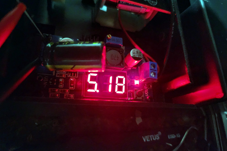
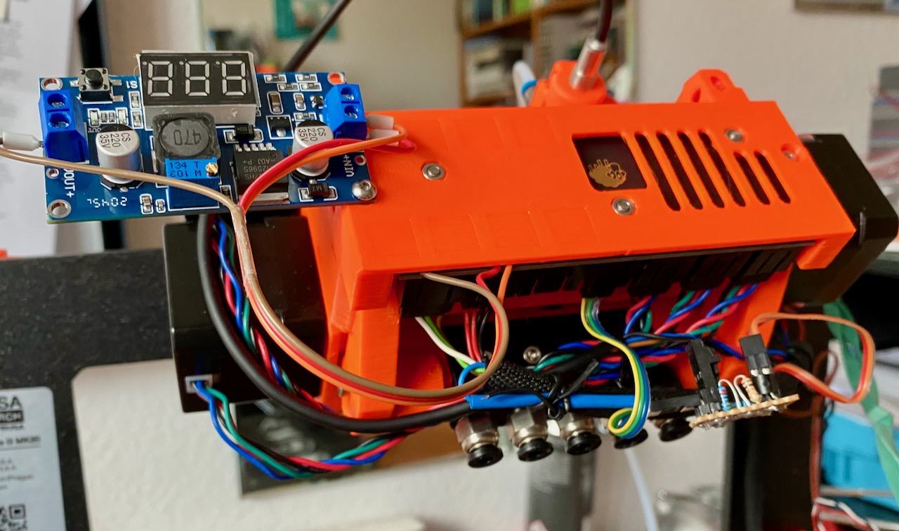
Finally I joined the club. After fixing intermittent "all lights flashing" errors with an external USB power supply for quite some time the problem started again a few days ago. So I decided to also install an DC converter and supply the MMU board with 5.2 V from it. Initial testing looks good, no failures during first test print...
I used one of the converters jsw posted. This is how it looks right now, casing will follow soon:

If at first you don't succeed, skydiving is not for you.
Find out why this is pinned in the general section!
RE: I found serious design error in MMU2 electronics hardware
And here is the case: https://www.printables.com/model/399513-dc-converter-case-for-mmu2-additional-power-supply
If at first you don't succeed, skydiving is not for you.
Find out why this is pinned in the general section!
RE:
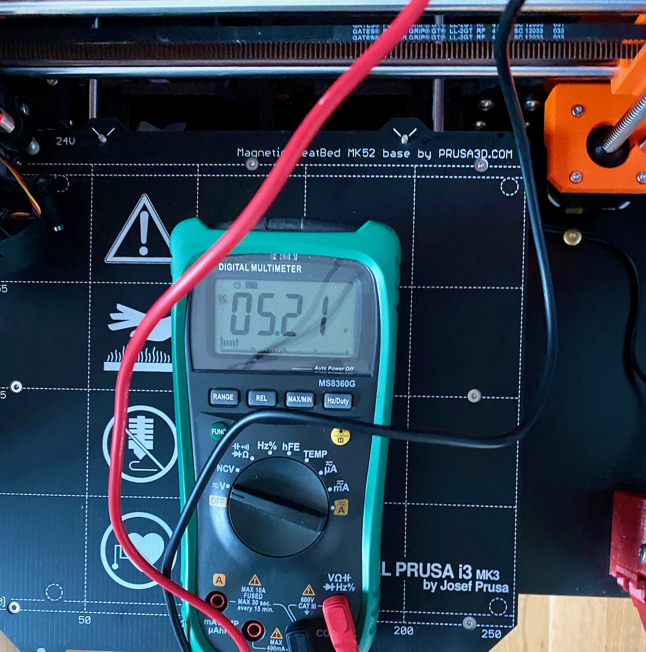
I checked my mmu with a multimeter. Before the diode D1 i have 4.9 V, after the diode 4.1V. When the pulley motor starts to rotate the bond tech gears, the voltage after the diode drops below 4V (3.91V). According to manual, then mmu enters the state with all lights lighting, "a state where Trinamic drivers were not able to provide enough power for steppers[... ] If the problem occurs three times in a row, the MMU2 unit stops printing and starts flashing continuously with red and green LEDs".
The low voltage i saw (3.9V) is caused by the diode D1 and, also probably, by the high temperature in my room (30 degrees Celsius).
Shorting the diode D1 resolved the issue (inserting usb power did not). Also now i can tighten the spring screws better (probably more power to the idler and pulley motors) without errors.
The bug is reported to devs, so you can subscribe to it:
https://github.com/prusa3d/MM-control-2.0/issues/15
Prusa said that "Our devs are finalizing new smarter firmware, which will bring new features along with improved performance and reliability to the MMU2S - all on the current motherboard[...] we're focusing on the elimination of restarts caused by low voltage"