RE: I found serious design error in MMU2 electronics hardware
The unplugging and plugging back in the motor cables, and the rest didn’t fix my problem (would have been nice).
As the video shows, the reset happens just after the selector motor reaches the filament slot, and from my recollection the idler would be the next motor to engage. So that would mean something is specifically happening to the idler motor and it’s not getting enough power?
(And I know that is not where the pyre tubes go, I just didn’t bother to put them in the holes in the plexiglass)
RE: I found serious design error in MMU2 electronics hardware
Hey all,
first of all, thank you so much for the investigation and the solution of this design error.
I ordered one of these bucks, directly soldered the input to the 24V pins of the MMU board. The output 5V went to the blue cable. I left the Out- blank, as I think I don't need it - I still get ground from the einsy.
I maybe made a bad mistake: To adjust the output, I started the printer without Einsy cable, so without ground connected. I might accedentially injected 17V for a short time. Maybe I fried it, but ground was not connected - so I don't know.
Now it was set to 5,2V/4,8V at D1. But the stepper do not move. I just hear a silent rustle noise. The MMU board seems to boot correctly.
Okay, I might have to order a new board - or what do you mean, can cause this noise?
I must say, it is hard to adjust the output of the buck - a slight turn makes a huge voltage difference.
kind regards,
RE: I found serious design error in MMU2 electronics hardware
I am having trouble visualising what you did. a diagram and/or photograph would help understanding.
RE:
@bryn51, sorry for the confusion.
I cannot edit the post, so here is a new one:
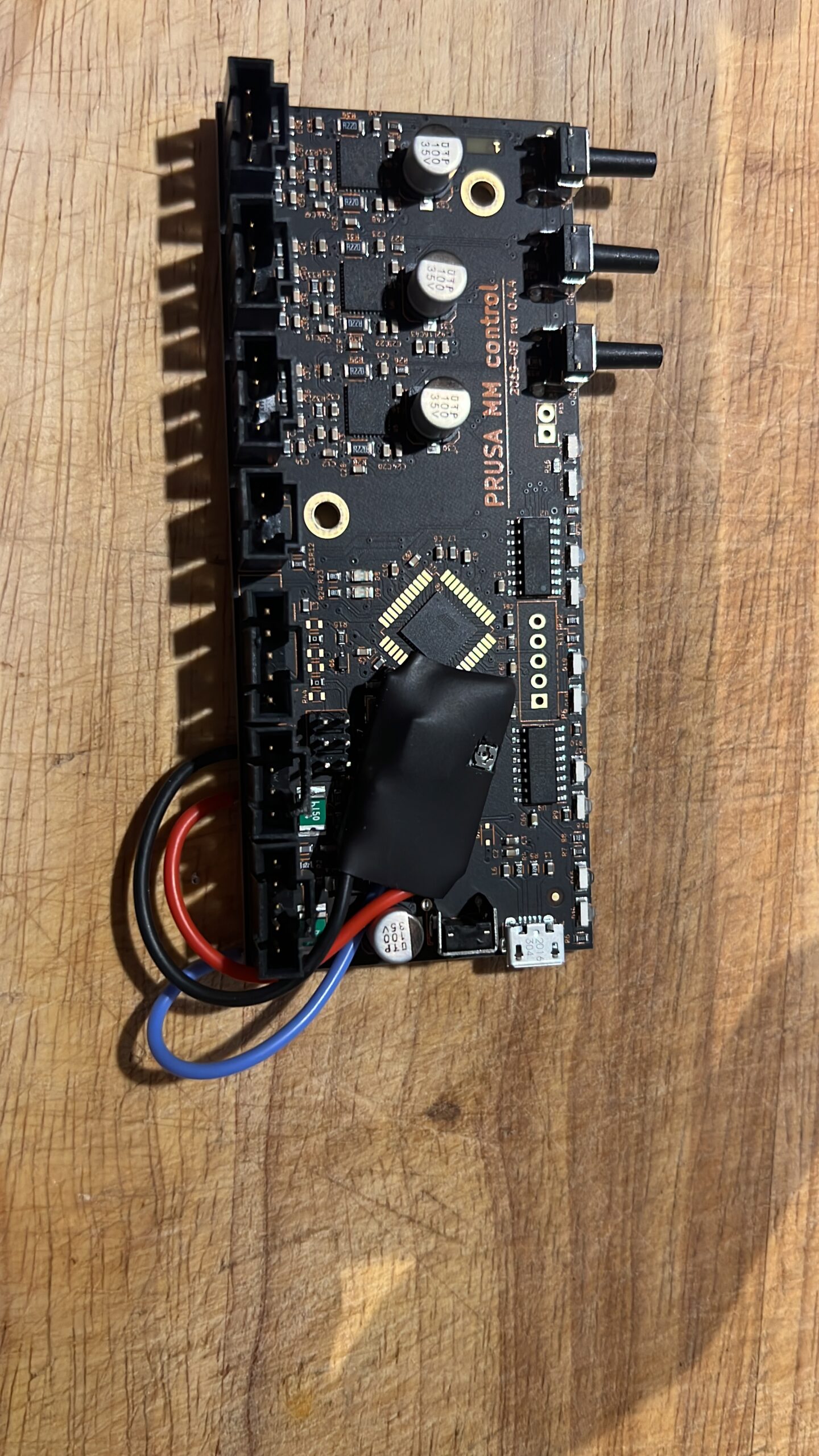
Basically, I copied the installation from many posts ago and used a MP1584EN.
- Input of the buck is soldered to the 24V pins of the MMU control board
- Output+ is soldered to the blue Einsy cable pin
- Output- is not used
It was a risky decision to leave the 5V cable on the board while setting the output. But I thought as long as I don't connect the Einsy cable to the board, I can safely make the adjustment. Also, I thought I had already set the potentiometer to the lowest voltage. But I measured 17V on the output and had to reduce it immediately. Maybe this damaged something, even with no Einsy-cable connected.
Overall, I was lazy and now, I might to pay for that. I just ordered a new board - keeping my fingers cross, that Prusa already ships out modified boards 🤣
The issue I have now is, that no stepper is moving, but they make a very silent noise, a quite rush.
RE: I found serious design error in MMU2 electronics hardware
seems like you are the second person in a few dats who has made similar error.
the correct procedure of course is to check and adjust the output voltage of the buck boost board BEFORE connecting it to your expensive Mcu board.
actions:
firstly you will need to connect output negative to ground pin for 5v rail.
there is a slight chance the high voltage may not have damaged the mcu board, but its likely you have. its easy to establish whether you have or not:
firstly having reduced the output voltage then check around the mcu board at accessible points to confirm the effect of adding in the booster.
secondly connect it all back together and test the printer and mcu and check for signs of life, including MMU operations. start up sequence, selector movement, and check the LCD display and see if the MMU firmware signature is seen under the support menu item. If its recognised you are in with a chance, as this means that the mcu chip itself is feeling healthy. But you will need a more extensive test of the mmu to check the trinamic driver chips are also feeling healthy. you know how to do that.
cheers
RE: I found serious design error in MMU2 electronics hardware
I have a set of spare cables and connected them, but I see the same behaviour. It seems that the board boots as normal, and it tries to advice the idler stepper to do the initialisation and homing, but there is nothing but some silent noise.
Also I can read the firmware version in the support settings. Someone mentioned the stepper fuses, that may recover from itself.
For the next try with the new board, is it okay to just connect the 5V Output to the 5V input and get the GND from the einsy?
RE: I found serious design error in MMU2 electronics hardware
Short update... I received a new MMU board and it works flawless with the original connection. Then I made new cables, since my MMU sits on top of the enclosure. I get the 5,6V directly directly from the 24V power supply and swapped the small bucks with a bigger DCDC buck from AZdelivery.
I read here and there that the small bucks tend to become hot and may explode (really??).
Now I have 4,9V after diode and I am quite happy now. I will start a 4-color print next week, then we will see 🙂
RE: I found serious design error in MMU2 electronics hardware
Jablake,
How would you add the voltage converters? I was wondering if my power supply was having problems putting out the proper current. I am not sure what the total amperage output should be from the power supply. Sounds feasible, as now none of my NEMAs are driving on the MMU2S.
RE: I found serious design error in MMU2 electronics hardware
What's the board revision on the new board you received? Thanks!
Short update... I received a new MMU board and it works flawless with the original connection. Then I made new cables, since my MMU sits on top of the enclosure. I get the 5,6V directly directly from the 24V power supply and swapped the small bucks with a bigger DCDC buck from AZdelivery.
I read here and there that the small bucks tend to become hot and may explode (really??).Now I have 4,9V after diode and I am quite happy now. I will start a 4-color print next week, then we will see 🙂
RE: I found serious design error in MMU2 electronics hardware
Again 0.4.4. and the same 1.0.6 Firmware
RE:
This fix worked for me. I soldered a 24V to 5V DC converter (TMR 2-2411WI) on to the back of the pcb, removed the series diode and printed a new cover with a hole for the converter.
Perfect filaments changes on my first print of the prusa lizard.
Thanks for sharing.
RE: I found serious design error in MMU2 electronics hardware
Crazy how this works great. I've had problems off and on with my MMU2 for probably 2 years. The first 2 years it worked great. I would reseat the MOLEX cables and it would fix it for a bit, but I noticed if I started even bumping the cables it would cause a problem. Tested the voltage. 4.96v from the board to the MMU. 4.23 after the D1 diode. Bought the mini buck converters off Amazon and adjusted it to 5.2v before attaching to the MMU. Voltage got to 4.84 after D1, but my MMU2 would stutter a bit, so I bumped it up until my voltage after the D1 diode was 4.92 and it's been working great.
It's definitely a problem and probably more of a long term issue than a brand new one. However, I can see if the cables aren't making good contact from the beginning it could be an issue up front.
RE: I found serious design error in MMU2 electronics hardware
I am also impressed how flawless MMU now works.
Interesting is, that there is a 3.13. firmware planned an it has the side note „New MMU“
RE: I found serious design error in MMU2 electronics hardware
After a few years of my MMU2 working great, I also have issues now. I guess I have to try this. Don't get why this shows up after a few years though, but since I'm not the only one....?
RE: I found serious design error in MMU2 electronics hardware
On the Prusa podcast a few weeks ago (maybe a month), the question about MMU was brought up. They very briefly said it's not just a software upgrade. It will be interesting to see what they come up with.
RE:
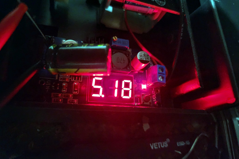
One very nice converter of this type that I've been using in all kinds of projects lately, available almost everywhere, has a three-digit built-in meter.
Just feed it 24 (or whatever) volts in, adjust the output to what you want. For the Pi/Arduino I usually goose it a bit just over 5v.
No muss, no fuss, and you can blank out the display by holding the button down.
I do usually add a mini heat sink on the one chip that runs a bit warm.

This fix worked for me. I soldered a 24V to 5V DC converter (TMR 2-2411WI) on to the back of the pcb, removed the series diode and printed a new cover with a hole for the converter.
Perfect filaments changes on my first print of the prusa lizard.
Thanks for sharing.
RE: I found serious design error in MMU2 electronics hardware
Hey - yet another victim of this after many many months of never seeing this (thus oxidation seems a good hypothesis as to the trigger of the issue in my case at least) - having read the detailed views of folk way more knowledgeable than me, I figure the optimum to solution is to go the deoxit route and see if this works as temporary crutch. Quick question for @bryn51 though - could you confirm whether it's Deoxit D5 or Gold you recommend? You mention gold is more just for protection and D5 is the one that chemically attacks the tin oxide, so I assume D5 is the one to go with here - hoping you might share some of your wisdom and confirm? Many thanks for all your insights and those of other knowledgeable folk - much appreciated!
RE: I found serious design error in MMU2 electronics hardware
regarding usage if deoxit here’s what I did once and never had to do-it again.
1. Apply deoxit D into the holes of tye female connector and let it sit there a good few mins (like 5-10). Deoxit G attacks the Tin oxide
2. apply pressurised “air” gas from electronics shop to blow away excess liquid.
3. wipe off tge female connector
4. apply deoxit G in the same way. Deoxit G is a protectant to try to halt further oxidation.
5. when plugging the female connector back onto the board push it in and out a few times. you are trying to shift remaining tin oxide from mating surfaces.
Whilst I had my doubts about this in the beginning after 6 months or so its proven to be long lasting. and I still have most of the deoxit, as only a few drops get used in the above operation.
RE: I found serious design error in MMU2 electronics hardware
Hello,
I have an mmu2s 0.4.4 card and I have disassembled this device because it was only able to flash all the green and red leds.
These messages explain that this is due to the 5V device being too low powered.
This device also has a direct 24V input on the third connector.
Is this a good method below ?
(1)- I cut the blue wire on the first connector (coming from the einsy board), a message seems to explain that it is the +5V rail of the einsy, I am not sure.
(2)-I take the 24V on the third connector : (+)=2 red wires, (-)=2 black wires.
(3)-I mount a annexe pcb with LM317 (regulator at 1.5A, common (-)) and 2 capacitors and I set it to 5.2 or 5.3 V
(4)- The plus (+) output of this regulator goes to the pin of the first connector (with the previous blue wire)
Is this a possible repair without error? Have I made a mistake?
Do I cut the good 5V wire ? Can a simple lm317 do the job ?
Have a nice day !
F. (from France, this deepl.com help...)
RE:
seems to me you have the right approach. I am not completely certain LM317 is perfect regulator to use but it should work. The type I use is referred to as “buck-boost” power supply.
But your approach should work.
when you have it wired together, connect it and power it up. check 5 v rail on MMU MCU board (look at circuit diagram available on prusa github ), and also check 24 v rail. if the voltages are correct your mmu should work better than before.
You can also apply deoxit D contact cleaner to the 3 x connectors leading to the stepper motors.
finally look at physical tuning measures for the mmu. this includes setting of PINDA and FINDA filament sensors, plus Idler tension on both MMU and Extruder.
there are just so many issues on mmu that cause problems, but when you get them right many say MMU can work great.