RE: I found serious design error in MMU2 electronics hardware
@Kugelfang
I would also be very interested in your solution as I have this issue very often.I already ordered the „MP1584 adjustable Spannungswandler“ from your eBay Link.
Could you provide me some more detailed information and/or images on how to install it?
That would be great. Thanks in advance !!
Hi Sebastian,
If you check page 4 of this tread you'll finde a lot of pictures that other posted. Basically the idea is that you steal 24V of the black and red connector and set the step-down to output 5V. Next you need to connect the 5V of the step-down to the where the original 5V supply was coming from the easy. I left the original 5V cable dangling isolated with some tape.
RE: I found serious design error in MMU2 electronics hardware
Add me to the list. I got my MMU2S working reliably in mid September (after much tinkering), and it worked well for a couple months. This past week, however, my MMU2S was failing with 10 blinking LEDs every time I tried to print, usually within the first handful of filament changes. I checked the voltage, and it was 4.96V at the "EINSY" connector pin, and 4.26V after diode D1.
I followed the same approach as was detailed in this post on page 4 ( https://forum.prusa3d.com/forum/postid/612964/). I used a cheap buck converter found on Amazon (search for "eBoot Mini MP1584EN DC-DC Buck Converter Adjustable Power Supply Module" if you are interested). I had to dial up the voltage from the DC-DC converter to around 5.48 volts to get 4.83 volts after the diode. I was able to push the pin with the blue wire out of the connector and not cut any wires, so I can undo the change should it ever need to be reverted.
So far, all is working. I've started a print with about 1000 filament changes. We'll see how it goes...
RE: I found serious design error in MMU2 electronics hardware
It would be interesting to hear the results. That’s the first time I’ve heard of a really clear deployment of the “voltage boost” correction. Most do not describe it so well.
RE: I found serious design error in MMU2 electronics hardware
I also did the mod and now have about 4,8V after D1.
My 20h Test Print with nearly 700 Tool-Changes now runs for almost 15 hours without any interventions.
That’s really great!!!
Before I did the mod I had a lot of issues even with Single-Color Prints.
I hope it stays like this.
RE: I found serious design error in MMU2 electronics hardware
In the meantime my print has finished without a single error or hiccups.
I am really happy and hope it stays like this.
RE: I found serious design error in MMU2 electronics hardware
👍 👍
wbr,
Karl
Statt zu klagen, dass wir nicht alles haben, was wir wollen, sollten wir lieber dankbar sein, dass wir nicht alles bekommen, was wir verdienen.
RE: I found serious design error in MMU2 electronics hardware
I have some buck converters and will do the mod soon, but in the meantime my mmu has not had the 'all leds blinking low power indication' since I put deoxit on the connectors. I was getting it almost every time I tried to print something (even single extruder)
RE: I found serious design error in MMU2 electronics hardware
Yes, that seems to be the thing.
we have the misbehaviour of the MMU, which despite the low voltage is able to operate OK, and then we have the connectors. If contact pressure and oxide is removed physically or by Deoxit, can fix the problem. And then we have the low voltage: its there all the time, but if the device is malfunctioning, increasing the voltage can also cure the problem.
So, one problem, two cures.
I think that fixing the connectors addresses a root cause, whereas the voltage level cure addresses the symptoms.
But its also possible that the circuit design is borderline and lends itself to increased voltage drop caused by poor connection (oxidation of contacts).
So the title of this thread is entirely accurate. The true root cause is the circuit design. Aided and abetted by the use of tin to gold interface in the connectors with oxidation of the tin side of the connection, and poor contact pressure caused by vibration of the connector and wiring loom. I think vibration does something to the inevitable tin oxide (perhaps causes a migration) that makes its effects worse. So, due to the design, there is no way that the MMU can be completely reliable as time elapses. Prusa could fix this by a few simple changes. But they seem to have washed their hands of this MMU concentrating their attention instead on a much better design found in the XL, with 5 separate extruders.
Perhaps a few hundred of MMU owners should visit Prague and shout loudly with placards outside Josef's office demanding attention to the issue and he will pay attention.
I have not yet seen a solution propagated by anyone that addresses the wiring loom vibration.
RE: I found serious design error in MMU2 electronics hardware
It would be interesting to hear the results. That’s the first time I’ve heard of a really clear deployment of the “voltage boost” correction. Most do not describe it so well.
The printer has been running continuously since my previous post. I would estimate 500+ filament changes. No recurrence of the 10 flashing LEDs.
RE: I found serious design error in MMU2 electronics hardware
I have some buck converters and will do the mod soon, but in the meantime my mmu has not had the 'all leds blinking low power indication' since I put deoxit on the connectors. I was getting it almost every time I tried to print something (even single extruder)
Which connectors, exactly, did you re-seat? The stepper motor connections to the MMU2S board?
I ask because I am now wondering if there is an issue with the harnesses running from the Einsy board to the MMU2S as well. The MMU2S BOM (here: http://htmlpreview.github.io/?https://github.com/prusa3d/MM-control-2.0/blob/master/rev.03/interactive-BOM.html) calls out the same headers with gold plated pins for all the harness connections but I don't recall the 5V pin I pushed out of the harness running from the MMU2S to the Einsy being gold plated. I'll have to take a closer look when this print is finished...
I did some further research and the Molex part number for the 4 position headers on the board with gold plated pins is MOLEX 70543-0003. The equivalent part with tin connectors is MOLEX 70543-0038. An ambitious person could desolder the existing headers and replace them with the tin parts.
Alternatively, the Molex part number for the stepper motor connectors with gold plated pins is 70400-1193. Again, one could cut off the existing connectors and crimp on the gold plated versions.
Which connectors, exactly, did you re-seat? The stepper motor connections to the MMU2S board?
I put Deoxit D on all of the connectors on the MMU board and on the 4-wire MMU signal cable connector at the Einsy board. I have Deoxit Gold on order.
RE: I found serious design error in MMU2 electronics hardware
... in yesterdays pursa live stream it was teased in the Q&A section that "its not just a FW update" for the MMU that is coming. fingers crossed this HW issue will be fixed and there is a upgrade path for existing devices MMUs
RE: I found serious design error in MMU2 electronics hardware
I got the all LED power failure blink yesterday in the middle of a 10 hour MMU print. I unplugged the Einsey board connector and it has temporaily solved it. I received my Deoxit Gold and will put it on the connector and add the buck converter. Hoping for a fix from Prusa soon.
RE: I found serious design error in MMU2 electronics hardware
Which connectors, exactly, did you re-seat? The stepper motor connections to the MMU2S board?
The connectors leading to stepper motors in particular have tin plated female pins connecting to gold plated male pins on the board.
the Finda probe connector has gold plated female pins.
not sure about the two connectors that go to Einsy board.
However when I investigated this initially on advice from @Jan Wieck I applied Dexoxit on all of them both Tin snd Gold plated female pins. I also pulled apart the stepper motor connectors and “adjusted” contact spring tension to increase contact pressure.
furthermore I purchased a swag of gold plated female pins, but did not install them.
the reason not to install new pins is that this entails shortening of the wires by a few mm, and a couple are already shorter than I would like. I also purchased some 22 AWG wire in different colors ready to replace the wires.
So the pins and wires likely will be replaced should the Deoxit evaporate one day and problem recurs. But to date the issue has not recurred (~3 months).
The reason I replace tin female pins with gold rather than vice versa is that the actual cause is naturally forming tin oxide being exacerbated by galvanic action in high humidity environment when pressed against gold metal. It builds up due to vibration of the wiring loom. The tin oxide is the actual demon here causing all the problems. Deoxit D is proprietary product that appears maybe to chemically hit the tin oxide. Not sure if it dissolves it or reduces it. Deoxit G is a protectant preventing further tin oxide from building up.
One must ask WHY the poor connection of the stepper motors leads to the symptoms we all observe. My understanding is limited, but I do know that the steppers do not contain any active electronics - no sensors. The driver chip just drives the motors in two phases. I think it must be monitoring the current drawn by the motor. When the (selector or idler) stepper is driven to the backstop as part of its self calibration, the driver chip senses an inductive spike produced by the motor coils to indicate the motor cannot move any further. If the connector covered in tin oxide is acting like a metal oxide diode then perhaps the spike cannot be seen by the driver.
Prusa teasing both hardware and firmware update for MMU? Its not the first time. Let’s hope they perfect the updates sooner rather than later. Meanwhile my order for the XL printer grows ever closer, promising an end to all this pain with the Mk3s+ and MMU.
Could the Einsy connectors be getting into the party ? Yeah I think so. Certainly it’s possible. The Einsy comms uses unbalanced serial communications, unshielded cable. Any noise will produce data errors.
RE: I found serious design error in MMU2 electronics hardware
So I bought a new MMU2S board...problem still exist...My selector doesn't move at all anymore....this is weird...and I'm at a loss on how to solve this...
RE: I found serious design error in MMU2 electronics hardware
So I bought a new MMU2S board...problem still exist...My selector doesn't move at all anymore....this is weird...and I'm at a loss on how to solve this...
As it turns out I'm an idiot who installed the old board back into the MMU2S, for now it seems to work...
RE: I found serious design error in MMU2 electronics hardware
So I just recently had the all lights flashing and constant resetting shenanigans. Was sent to this post and hooked a 24v DC to DC converter on to my printer. Well I figured the converter would start at zero volts and as you turn the screw it goes up. But no, it’s the other way starting at 24V and going down. So now my Mk3s is not detecting the mmu, I think.
When I go to support and scroll down it says mmu n/a, which I think means it’s not detecting it?
I have it set to 5V exactly now. I don’t know how to check if the board is fried, if it is fried or if something else might be wrong.
I have checked the manuals online and I have the mmu wired to the printer correctly.
As for the DC to DC converter, I added a wire and connectors from the 24V coming from the psu to the printer, from there to the “in+” and “in-“ of the converter. Cut the blue wire on the mmu cable that comes from the einsy board to the mmu, put that in the out + and spliced into one of the negative wires coming from the mmu going to the einsy and hooked that to the out - on the converter.
If you can help thanks!
RE:
I’m having trouble working out what you have done and what level of electronics expertise you have.
it does seem like you have jumped in with not much expertise or experience.(sorry to be so blunt). Please don’t take that comment personally.
for a start did you access the circuit diagram for that MCU board from Github ? The diagram indicates the types of component and you can check out the specs of each via Google.
secondly where exactly did you connect that 24v buck boost converter to the circuit? Why did you not measure the voltage output if the buck boost converter before you connected it.?
If you happened to hook 24 volts up to the 5 v supply from Einsy to MMU MCU it’s likely you fried the MMU MCU board. But you can check that on the circuit diagram. You also maybe fried the Einsy board. But that’s easy to check as it has the LCD display.
I suggest that you need to take a somewhat more cautious approach to what you are doing.
I’m not going to offer more at this point because I do not have the board and circuit in front of me.
I’d say that this illustrates the folly of trying to implement somebody’s suggestion given in very vague terms on this and other forums, without fully understanding what you are doing.
- Buy yourself a new MMU MCU board. Odds on its fried.
- measure the 5v rail from Einsy board against the 0v Gnd line from the same source.
- connect the 5v from Einsy board into the input line of the buck boist converter and the zero volts line also. Check polarity of both.
- adjust the output voltage of the buck boost board against its Gnd. Adjust the voltage until it’s 5.0 volts exactly.
- then you can safely connect the output of the buck boost to the MMU MCU to the same connector pins that the Einsy 5 v and Gnd used.
check the points around the MMU MCU where 5v rail should appear. Is it 5v ? No? You may then be able to slightly increase the buck boost output until the voltages around the board are I.r.o. 4.8 volts. Then package it all up cuz you are done.
then it’s time to test. See if the original problem is gone…
That, so far as I am aware, is what the guy earlier in this thread was trying to say in a much briefer explanation.
if the problem isn’t gone then I suggest that this cure is not the appropriate one for your issue. You could try cleaning the contacts in the 3x stepper motor connectors using Deoxit. I have personally deployed this solution and it worked for me. And it’s far far simpler and cheaper than what you have chosen to do.
RE: I found serious design error in MMU2 electronics hardware
So, I turned my printer on today, and now the mmu is responding, I did nothing but turn it off and back an between when I posted the last response and now. But I still have the problem of it resetting, I upped the voltage to where after the D1 diode now has 4.9V but yet the problem still persists.
Also, I have some basic wiring knowledge, and don’t know a whole lot about electronic boards.
RE: I found serious design error in MMU2 electronics hardware
The MMU has a 150mA fuse on it, and the size is 1812. I'm guessing that this fuse is a PTC type. In other words, instead of blowing and rendering the board useless, the fuse will reset after a while. This may explain why the board appears to work now. However, fuses are not infallible, especially slow-as-snot PTC fuses. There's a good chance that the board is damaged and there isn't a good way to determine if that is the case or not. You'll have to work on getting the board running again and then slowly building confidence as it continues to work. Which, may not be possible.
You're currently in a decent spot (would be in a GREAT spot if your board wasn't possibly blown the hell up!) to test a theory.
- Can you record a video of the MMU when you power up the system? My MMU would do a couple of things then fail when I was having issues with it. I believe that one or two of the motors was working fine, then when it tried to drive the "bad" one is when the MMU failed. I saw it try a few times before giving up and it gave me some clues to look at while I was digging through the firmware source code. A video may prove to be helpful, but isn't critical at all.
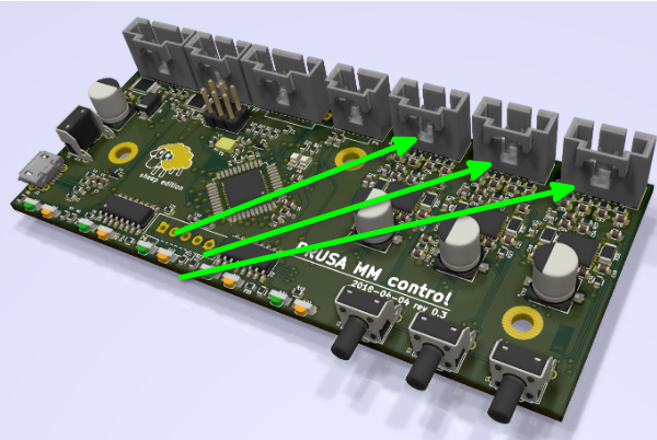
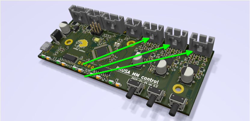
- Unplug the motor cables from the MMU, and plug them back in. Do this half a dozen times or so. If there is any oxidation on the pins, this will clear it off. It is likely that even a single unplug and replug will do it, but go ahead and do it a few times. Please be aware that the board is installed upside down. You want to exercise the cables that are on the same end of the board as the buttons.
- Please complete step #2 and try the board before proceeding to step #4
- If the MMU is still failing, also try unplugging and replugging the rest of the connectors on this board, then test again. I don't expect this to fix anything, honestly, but it is a last ditch effort and doesn't cost anything.
Several members that have posted in this thread believe that a significant contributor to this failure is oxidation on the pins in this connector. I'm squarely in this camp. You've already bumped the voltage up to ~4.9v and that hasn't resolved the issue. Unfortunately, we can't be certain that the 24v joy ride didn't cause some damage as well.