RE: I found serious design error in MMU2 electronics hardware
I also faced the same problems with the flashing 10 LEDs, as info, my MMU unit is from a time when it came on the market and is board rev.03. I measured the +5V voltage on the MMU-board, which was 4.27V, as already stated, too low for safe operation.
I had a closer look into the schematics ( https://github.com/prusa3d/MM-control-2.0/blob/master/rev.03/MM-control.pdf ) and looked for the best solution of the problem. In my opinion, bridging the diode D1 is the easiest, cheapest and best solution to this problem. After the bridging I can measure 4.65V, and I could not observe the problem anymore since then.
I want to discuss possible problems with this approach:
- D1 provides reverse protection against swapping +5V and GND: not really an issue, as the MMU is connected permanently to the Einsy mainboard, therefore no occasionally swapping should occur
- D1 provides reverse current flow protection, so that my by USB connected PC cannot power the whole Einsy mainboard. That is theoretically true, but only when the diode D7 next to the USB-Port is in place, when this diode is missing, its not even possible to power the MMU board by a connected PC, as the only place where the VBUS voltage from the USB connecter is going is to the VBUS-Sense input of the MCU which is only used for sensing if a USB cable is connected or not, BUT not to power anything. On my board, diode D7 is not populated, therefore, there is no reason why bridging D1 could lead to any problems in my eyes.
The interesting part is, that also on all PCB-pictures in this thread, the diode D7 is not populated, so it seams to be common. When this is true for all units outside, the solution with an external USB wall-charger should not help at all. Maybe also the reason, why the USB wall-charger solution also only helped temporarily for most people.
RE: I found serious design error in MMU2 electronics hardware
Can confirm. No D7 on my MMU, and it won't power via the USB. It reqiures printer power to work/firmware update.
I'm going to bypass the D1 (and make sure I don't mix positive and negative. :D)
RE:
I confess not reading every post in this 2y/o thread. But I got my MMU2/s in March 2022 and still I have had the symptom where Idler behaves erratically and sometimes the other two steppers also (but harder to spot. )
I took a different path to correction: It was noted by myself and others that the condition was influenced by movement of the wiring loom. In operation, the loom can vibrate. It has more mass than the wires supporting it, so it moves up and down, and the lever arm of individual wires to connectors moves also. So the connector is vibrated. It has tin contacts against gold contacts on the board. So vibration can cause noise and intermittent contact.
But likely it would not be such a problem if voltage was correct, so the issue you found with the voltage could be working hand in glove with the contact issue. The contact issue is solved using a contact cleaner and protectant Deoxit. But likely this is temporary fix because the protectant can evaporate over time.
So I plan first to verify that the low voltage condition still affects the MCU board I have from March ‘22. I am avoiding it because it’s not easy to get in there even with small probes.
I have already created and shared with Prussia some documentation about the MMU2, and so I can update that. Modifying the board either by playing with diode or adding a boost voltage is not something I favor, as it cannot be completely reliable.(IMO).
so what is the best solution? The mk3S+ Power supply must already be running close to its limit, the reason we see regulated voltages dropping below threshold. Then there are multiple places voltage can drop toward the MMU MCU board. So, I’d be looking at raising the 5v rail slightly if it can be adjusted. Perhaps it has component tolerances affecting the voltage delivered, and they could be tweaked with high accuracy (1%) components.
addition of a buck/boost chip could improve operation.
this is speculation…
I’ll post back here with results of my validation tests on “current” hardware (unintentional pun).
thanks to all those people that posted here in the last two years. It provides provenance that supports case for Prussia Research to take some action.
In the background is the unknown effect development of the XL printer has on the future of MMU. I think the Mk3S+ still has a life because the XL is such a high price. And with it, the MMU. So IMO. it’s worthwhile for Prussia to provide a pathway for correction of this issue which appears widespread. A replacement/upgrade to that MMU/MCU board appears justified.
cheers to all and happy printing.
RE:
I barely know anything about electronics. Although, I am pretty good at finding a logical solution to problems. Yes, I am pretty certain there is an issue with the MMU unit based on power.
Bryn51 write: "The contact issue is solved using a contact cleaner and protectant Deoxit. But likely this is temporary fix because the protectant can evaporate over time."
This is exactly what I discovered. When I have excessive instances of the all LED flashing I power down and take off the terminal from the MMU to the EINSY board and clean the terminal as best as I can with my wife's emory board and a little DEOXIT. This works fine for a month or 2.
My thought is that Prusa should use better connectors. Instead of a friction type of connector, a screw in board would be more effective.
Now I just broke one of my favorite adages: If you say nothing, no one knows that you know nothing... 🙂
I spoke to Prusa Support about the Stepper motor connectors because I had formed the view that cheap tin plated female connector pins in contact with gold plated pcb make pins was not helping. Their response was that this was a decision of the stepper motor manufacturer based on cost grounds, and unlikely to change anytime soon.
personally I went out and bought some gold plated Molex pins with intention to change them and see if it helped. But didn’t proceed because there is another issue. When you change the pins the wire’s must become 10 mm shorter. It’s ok for two of the steppers, but the selector stepper is problematic because it’s already too short and taut..
I’m now waiting to see just how long the Deoxit lasts, and will revisit the decision then.
meanwhile I am also investigating the low voltage alleged by others. I am wondering if the power supply model has any bearing on this issue. Mind is the black type.
RE:
Ok. Today I made some measurements on my MMU2 using an Oscilloscope that has DVM facility.
findings:
To voltage of 24v supply from Einsy to MM control board: ~ 20v (loaded)
voltage of 5v supply from Einsy to MM Control Board: ~5.0 volts (unloaded/disconnected)
voltage of internal 5 volt rail measured at LED mux extension point: 4.2 volts.
I therefore suggest that the base premise that internal 5v rail in MM Control board is Low is confirmed on hardware supplied by Prusa to myself in April 2022.
I also checked data sheets for the MCU, and found that the fact this low voltage is likely to cause problems is confirmed.
the data sheet for the stepper motor driver chips indicate that the 20 volt actual supply on 24 volt rail will not be an issue for the driver chips, however I suggest that it may be an issue for the stepper motors, giving them reduced driving force.
recommendation: Prusa really need to review the design of the board with a view to improving the compliance of 5 volt rail, since it’s almost 20% less than nominal. Similarly the 24 volt rail is also low by the same percentage. Given that other stepper motors in the printer were inactive at the time, this is cause for greater concern.
Given that significant numbers of users complain of reliability issues with the MMU affecting customer satisfaction somewhat, action by Prusa is strongly Recommended.
failing that the possible user remedies include investigation of the PSU to see what can be adjusted to increase the 24 volt supply and 5 volt supply to be closer to nominal values, given voltage drops found in the system. For example PSU 5 volt could be adjusted to 5.2 volts.
secondly users could add a supplementary 5 volt supply, to be directly connected to the 5 volt rail using the connection point (pins 1 and 5) on the mm control board adjacent to the LED mux chips. Such supply could be derived from the 24 volt feed.
alternatively a source such as Octopi board could be connected via usb to the mm control board.
RE: I found serious design error in MMU2 electronics hardware
Nice work!
RE: I found serious design error in MMU2 electronics hardware
Pragmatically speaking, what do we have to do to get Prusa to fix the problem on the new units and correct it on the legacy units we all have?
RE:
Pragmatically speaking, what do we have to do to get Prusa to fix the problem on the new units and correct it on the legacy units we all have?
Hmm well I would very much hope for the first thing you mention, but as for the second thing I would not hold out much hope. What’s reasonable is for a kit of parts that can be purchased perhaps, and a firmware update.
In fact there have been strong rumours of such a firmware update by none other than the man himself, Jp. by way of the Prusa podcast #45 (YouTube) last week, at about the 1 hour mark. What’s in that other than the “refactoring” he mentions? No idea.
Part of the problem is there are very many people who claim to be satisfied customers, but when you probe, you find they experienced the same sorts of issues we all have, and it is just they don’t wish to complain. I think if everyone is honest, those issues are pretty much universal experience. But the fact so many are in denial means there is less pressure on Prusa to get it fixed.
But nobody actually knows how widespread are the various issues, because (as far as I am aware) there has never been an independent public survey of MMU users.
ultimately it’s going to come down to a commercial decision by one J. Prusa.
RE: I found serious design error in MMU2 electronics hardware
I'm what I would call a 'semi satisfied' customer of the MMU2S, but I admit that I haven't used it that much since I got a dual extruder printer back in early 2021.
When I do use it, however, it's usually well-behaved, but I take it out of the enclosure, set it up on the spare bedroom floor, and use the room space as the filament buffer.
I do admit that it is not as robust a product or as user-friendly as the MK3S printer. It is finicky and everything has to be just so for a good print. I would never leave it unattended for even a few minutes.
The assembly instructions were not as detailed as those for the MMU2S. Besides, the guy who sold it to me (open box, otherwise untouched) swiped the bears! 😉
Your voltage drops are concerning. I always think of something around 4.2 for logic circuits as out of tolerance and an invitation to malfunction. However, IIRC, all/most of the semis on the MMU2S board are CMOS, which has quite a bit of breathing room as far as VCC is concerned. IIRC it's driven by a Mega 32 chip, and I know some controllers run that chip at 3.3v for VCC with no issues, so that is probably NBD, at least with that chip.
My Big Burning Question to those who suspect that low supply voltages are causing an issue, has anyone actually tried using, if only temporarily, a substitute power supply or supplies that will deliver the correct voltage(s) at the MMU2S box, and if so, did that correct the issue?
RE: I found serious design error in MMU2 electronics hardware
Regarding the last, you will find such posts much earlier on this thread.
there are various:
- bridging D1 diode
- one guy promotes the idea of adding a small pcb that’s z voltage converter to produce a 5 volt supply.
- there’s talk about adding power via USB connector but I do not believe it can works as per the circuit diagram due to a diode that has an even larger forward voltage drop. But some say that diode is not actually fitted. I’m going to try it anyway.
- I hear what you say about 3.3 volts being more normal on an ATmega32u4 but I’m think that they have used a 5 volt version here. The reason would be the trinamic driver chips that want 5 v logic.
RE:
I admit that I did not re-read the entire thread prior to posting that.
The OP claimed that he boosted the voltage by shorting the diode and that corrected the issue.
If I were doing this (which I probably will not, as mine does not seem to be affected by this issue) I might try one of those inexpensive buck/boost converters (sounds like what you mentioned). I've used them in some RPi projects to boost a sagging 5v supply to drive a video display. They are only a couple of US dollars and are adjustable.
RE:
I have installed this power supply and usually have no problems regarding MMU2S malfunctions.
Additionally I have equipped the power supply of the MMU2 with thicker multi-core copper/silicone wires (lower internal resistance).
Maybe a separate, linearly controlled 24V power supply for the MMU2S could help too.
On my MK3 Klipper printer I replaced the Prusa board of the MMU2 with a BTT Mini E3 V2.0, which runs absolutely stable.
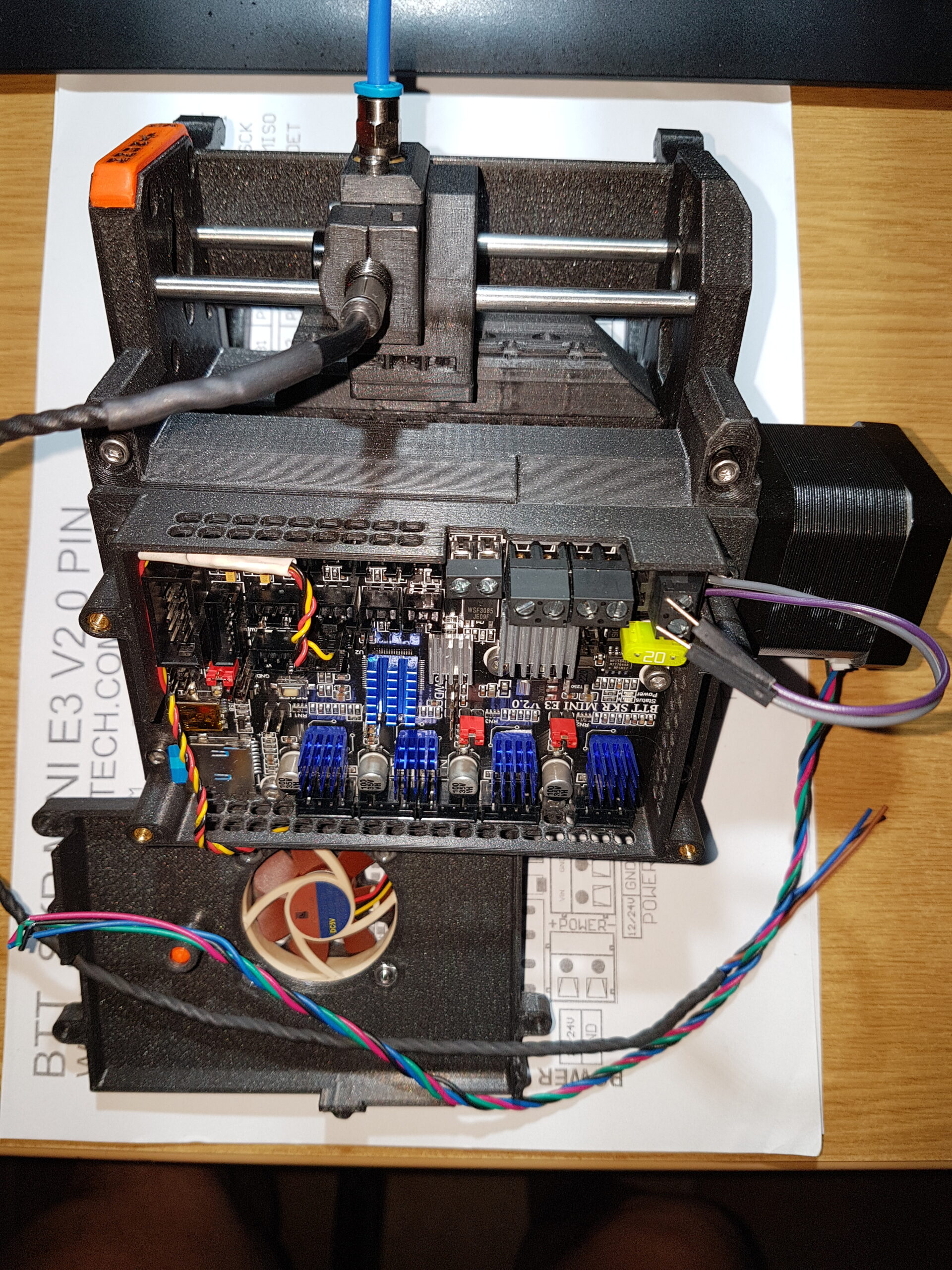
(Image during test phase)
Maybe this board can be integrated into the MMU2 with relatively low effort (Prusa firmware adjustments)?
wbr,
Karl
Statt zu klagen, dass wir nicht alles haben, was wir wollen, sollten wir lieber dankbar sein, dass wir nicht alles bekommen, was wir verdienen.
RE: I found serious design error in MMU2 electronics hardware
@jsw: I had the issue with the MMU acting up (all lights blinking) for months. Since I installed a step-dow using the 24V rail to generate 5V I'v not had the problem once again. I did before try the USB power supply (which did not help in my case). So my clear recommendation would be to invest 3€. this is what I used: MP1584EN Spannungsregler
RE:
Yeah well that’s the thing with this whole thread. Like many things on the MMU things go wrong that make no sense. And among them this voltage issue. Yes looks like every single mm control board out there has the low voltage. But only a percentage display issues that it apparently causes.
on the other hand when I cleaned contacts going to stepper motors using Deoxit it had an immediate beneficial effect.
But the various people with voltage correction solutions also say the same thing, :: problem solved when 5v rail is raised closer to its nominal value.(by any of the various ways ).
So …. I think that If there is a single phenomena behind all this it has not been definitively exposed by all our collective work. In fact it might not be just one fault but several. The best we can recommend is for people to try the different solutions and adopt the simplest solution that work in their case by way of Occams Razor logic.
RE: I found serious design error in MMU2 electronics hardware
This issue first seemed to affect me back in July, or at least I came home to a completed print with the filament still in the tube. It appeared to have failed while the filament was being retracted. I rebooted the printer and it started working again.
About a month ago, I couldn't get my MMU to do much of anything, even after a power cycle. The selector motor wasn't even trying to run. In fact, the MMU just kept doing what appeared to be repeated reboots. I wasn't even hearing the "thunk thunk thunk thunk thunk thunk" sound of the idler drum being driven against its limits. I removed the two tensioning screws, vacuumed out the little bits of filament from the MMU, and exercised all motors by hand manually. When I put it back together, it worked. I never felt as though vacuuming fixed it, but instead felt as though it was because I ran the motor by hand (more on this later).
About a week ago, I had a print that I just couldn't complete. It was a simple two color, two hour print with about 6 filament changes. It took me about seven attempts to get the whole thing printed as it just couldn't get through it without all LEDs blinking. I just kept trying, and eventually it succeeded.
Yesterday, I had another similar issue. It again was a simple print, though longer, but still about six filament swaps. At first, the MMU selector was trying to home, but failing. It'd be driven to the limits and bounce off the wall a few times, then move to position 1, then it'd repeat the process again and again. Eventually it'd error out and all LEDs would blink. I kept retrying, and the print kept failing on filament change. About a month ago, I finally broke down and bought me a nice Hakko soldering iron. This was a great opportunity to go ahead and replace D1. I checked the voltage of the 5v rail and it was at 4.283v. I shorted D1 and the rail was at about 4.8v afterwards. The printer is also running great now. However, I'm even less convinced of the 5v rail being the culprit now.
Yesterday, when the print would fail, it'd fail when trying to feed the filament forward. The MMU would "restart" and home the selector, I can't remember if it'd rehome the idler, but then it'd restart the homing process. It'd do this a few times, then it'd error out. I never saw the pull motor (the one that feeds the filament forward move). I didn't get the impression that the MCU was rebooting because the process just didn't feel like the same one that was being used on a power up. Also, I'm not sure what would cause an MCU to not care about the voltage rail being below 4.3v after over a year of ownership.
So I started thinking about corrosion. Bryn51 already commented on vibration with gold and tin contacts causing intermittent connection. What is being described by him is called "fretting" corrosion, and it doesn't require gold. Tin oxidizes almost immediately when exposed to atmosphere, but this oxide is very soft. Vibrations can cause the connection to slip, just a bit, and it'll cut into the oxide and push it aside. Over time, the vibration and pushing of the new oxide out of the way can cause the oxide to build up. Eventually, there's enough oxide there to cause the contact to become separated. Unplugging the connector and plugging it back in can clear the oxidation layer.
If what bryn51 says is correct, the tin contacts on the motor cable crimps against the gold plating of the board's connectors is a terrible no-no. Many young engineers make this mistake, "Gold doesn't corrode," but fail to realize that gold will cause the tin to also corrode. This is known as galvanic corrosion, and galvanic corrosion is sped up with heat. My MMU is inside of an enclosure which is at 92ºF. Again, just like with fretting corrosion, cycling the cables will clear this corrosion. Using a contact cleaner like Deoxit will work even better to clean the contacts.
I think the "fixes" I've done to the printer over the last few months always involved significant physical manipulation of the MMU. I opened the top and vacuumed out the filament bits. This required me to put a fair amount of pressure on the cable bundles to open it up all the way and easily could have been enough movement to clean the contacts a bit. Shorting out D1 requirement to completely disassemble the MMU's control board from the MMU. This certainly was enough movement to clean the contacts. This scenario makes more sense to me than my MMU's MCU suddenly caring that a voltage was slightly out of specification.
But it doesn't answer why the corrosion (whether fretting or galvanic) is an issue, why does it cause the LEDs to blink?
I started looking at the firmware and found a few interesting things.
First, there's this function:
//! @brief Unrecoverable hardware fault
//!
//! Stay in infinite loop and blink.
//!
//! LED indication of states
//!
//! RG | RG | RG | RG | RG
//! -- | -- | -- | -- | --
//! bb | bb | bb | bb | bb
//!
//! @n R - Red LED
//! @n G - Green LED
//! @n 1 - active
//! @n 0 - inactive
//! @n b - blinking
void unrecoverable_error()
{
    while (1)
    {
        signal_drive_error();
    }
}
Quite simply, that's an infinite loop with all LEDs blinking. But how do we get there? There's several ways...
//! @brief move idler and selector to desired location
//!
//! In case of drive error re-home and try to recover 3 times.
//! If the drive error is permanent call unrecoverable_error();
//!
//! @param idler idler
//! @param selector selector
void motion_set_idler_selector(uint8_t idler, uint8_t selector)
{
    if (!s_selector_homed)
    {
            home();
            s_selector = 0;
            s_idler = 0;
            s_selector_homed = true;
    }
    const uint8_t tries = 2;
    for (uint8_t i = 0; i <= tries; ++i)
    {
        int idler_steps = get_idler_steps(s_idler, idler);
        int selector_steps = get_selector_steps(s_selector, selector);

        move_proportional(idler_steps, selector_steps);
        s_idler = idler;
        s_selector = selector;

        if (!tmc2130_read_gstat()) break;
        else
        {
            if (tries == i) unrecoverable_error();
            drive_error();
            rehome();
        }
    }
}
So if get get a 0 response when reading gstat, everything is golden, else we can get an unrecoverable error. Gstat returns non-zero if any of the motor drivers have reported a reset, charge pump undervoltage, an overtemperature condition, or if a motor winding is shorted. If these were brushed motors, then I could see a short condition being cleared when I manually turn a motor, but I don't think that can happen with a stepper motor. I haven't worked out in my head how one of these four conditions can occur due to an open circuit on the connector, but that's where I'm leaning. There are ways for these motor drivers to report opens, but I'm not seeing where that type of failure is being read.
There's still more firmware to go digging into, but my kids are awake. I got to go and do some responsible things now. But, I'm strongly considering getting some dielectric grease to pack into my connectors. Tin and gold is a terrible combination, and blaming it on the motor manufacturer is bologna. Deoxit, I believe, is a lubricant more than anything else, and does help with preventing fretting corrosion. But I don't think that it can really deoxidize anything (please correct me if I'm wrong) as it doesn't contain any acids. I think this means it isn't expected to help with galvanic corrosion.
The next time this happens, I'll try to reproduce it multiples in a row. If I can, I'm planning on cycling all motor connectors on the MMU without powering the system down. I'll just cycle them, then hit the reset button on the MMU, and then try another print. If that resolves it, I think that'll strongly point to some type of corrosion on the pins.
RE: I found serious design error in MMU2 electronics hardware
I liked that reply. It’s a deeper analysis than my own.
unfortunately there is the Stepper motor driver chips to factor into the equation. The motor directly connects to those chips. So it’s a question of how the o/c condition or effective “contact bounce” pulse condition is seen by the driver chip and what it tells the MCU as a result. There is no actual sensor in the idler stepper motor (I opened one) it’s just two coils, no smarts at all.
RE:
@Kugelfang
I would also be very interested in your solution as I have this issue very often.
I already ordered the „MP1584 adjustable Spannungswandler“ from your eBay Link.
Could you provide me some more detailed information and/or images on how to install it?
That would be great. Thanks in advance !!
RE: I found serious design error in MMU2 electronics hardware
I've had the same issues. I tried all of the normal stuff and finally used Deoxit on the MMU connector on the EINSY board. After getting it printing 20 minutes ago. I started searching for solutions to poor MMU connection and found this thread. Put me on the list of customers with problems that hasn't contacted Prusa support (before GPS, I wouldn't stop and ask for directions either). When I have time I'm going to try to tighten the female connectors and probably add a 24V to 5V buck converter too.
RE: I found serious design error in MMU2 electronics hardware
@Kugelfang
I would also be very interested in your solution as I have this issue very often.I already ordered the „MP1584 adjustable Spannungswandler“ from your eBay Link.
Could you provide me some more detailed information and/or images on how to install it?
That would be great. Thanks in advance !!
You can get a six pack of them from Amazon for $6 with free Prime shipping.
6 Pack Mini MP1584EN DC-DC Buck Converter, Melife 3A Power Adjustable Power Supply Module 24V to 12V 9V 5V 3V Step-Down Power Module