adventures in assembly, comments on building instructinos...
I'm following this: https://manual.prusa3d.com/Guide/1.+Idler+body+assembly/756?lang=en
> Step 1, 3, 4, 5, 6, 9.
Missing hydraulic press. I used a wood clamp. With the parts I got it was not possible to use human power alone to push everything in; a hammer is probably not recommended.
> 3. There are small openings on both sides of the idler, which can be used to push the shaft back.
This is a lie; the ball bearings are blocking (half) of this shaft, making disassembly impossible - they all lock in each other now. These shafts should be moved slightly so that they don't hit the ball bearings.
> 12. Slide two screws M3x10 in the opening on idler-body and tighten them slightly.
I recommend not tightening them at all or start on the underside, which is the hardest one to align.
> 15. Make sure the shaft rotates freely. The rotation is limited by stops, but within them it should be smooth.
It's not smooth, it's a stepper motor...
Re: adventures in assembly, comments on building instructinos...
> 21. Carefully place the blade in the prepared cutout and align it with the top left corner.
My cutout was barely visible, certainly didn't guide the blade. Printing issue? I tried aligning it, not sure if it will be an issue later, part is now slightly thicker than intended?
> 22. Ensure the shafts are aligned with the pulley-body and move the selector-finda all the way to the left.
My selector did not move very freely, probably because of the above issue. Not sure if this will be an issue later.
> 26. turn the sensor counter-clockwise
I found it really hard to have tension on the sensor enough so that I could screw it, but not just pull it out.
It seems 26 would be easier to do with putting in a filament, then gently push down the sensor on the ball, _now_ tighten a little, rotate ccw 90 degrees, tighten.
> 29. Push the bearing in. Make sure it is aligned with the pulley-body.
Needed a hydraulic press for this one again. I mean wood clamp...
Re: adventures in assembly, comments on building instructinos...
I'm following this: https://manual.prusa3d.com/Guide/1.+Idler+body+assembly/756?lang=en
> Step 1, 3, 4, 5, 6, 9.
Missing hydraulic press. I used a wood clamp. With the parts I got it was not possible to use human power alone to push everything in; a hammer is probably not recommended.
> 3. There are small openings on both sides of the idler, which can be used to push the shaft back.
This is a lie; the ball bearings are blocking (half) of this shaft, making disassembly impossible - they all lock in each other now. These shafts should be moved slightly so that they don't hit the ball bearings.
> 12. Slide two screws M3x10 in the opening on idler-body and tighten them slightly.
I recommend not tightening them at all or start on the underside, which is the hardest one to align.
> 15. Make sure the shaft rotates freely. The rotation is limited by stops, but within them it should be smooth.
It's not smooth, it's a stepper motor..
> 21. Carefully place the blade in the prepared cutout and align it with the top left corner.
My cutout was barely visible, certainly didn't guide the blade. Printing issue? I tried aligning it, not sure if it will be an issue later, part is now slightly thicker than intended?
> 22. Ensure the shafts are aligned with the pulley-body and move the selector-finda all the way to the left.
My selector did not move very freely, probably because of the above issue. Not sure if this will be an issue later.
> 26. turn the sensor counter-clockwise
I found it really hard to have tension on the sensor enough so that I could screw it, but not just pull it out.
It seems 26 would be easier to do with putting in a filament, then gently push down the sensor on the ball, _now_ tighten a little, rotate ccw 90 degrees, tighten.
> 29. Push the bearing in. Make sure it is aligned with the pulley-body.
Needed a hydraulic press for this one again. I mean wood clamp...
1) use a center tap. you can lightly knock the shafts into place using a center tap and just the back of a piler body in place of a hammer you can also clean up the holes with a MM drill bit set just lightly clean it up by hand.
3) you take the assemble apart inverse order, first in is last out. just use a center punch to knock out the shafts from 5 back to 1.
and assemble 1 to 5.
12) clean out the elongated holes for the springs the inner bridging during the 3d print clogs up the bottom of the holes and does not allow the lid to float nicely on the spring. carefully follow the shape of the elongated holes and do not cut the lip off at the bottom that the spring perches on.
15) before installing the stepper you want to make sure the pulley assembly rotates free. the bearings have to be centered in the slots which will require moving the bearing assembly back and forth getting a sweet spot. the PETG is stringy so you have to clean out the slots i use a flat edge hobby knife to get rid of all the burrs that will make the assembly lock up and not rotate correctly.
21) agree Prusa needs to change this part they need to increase the depth of the knife outline so it sits nice in the clamp and doesn't move around.
put a small drop of crazy glue on the back side of the knife top, align to the shape and let the glue setup for a second this will keep the blade from shifting while you install the clamp cover and tighten down. on blade replacement you can chip off the glue with a razor blade. by then prusa might put out a selector revision part to fix this.
22) you might need to clean up the shaft holes with a MM drill the shafts need to float parellel and they can get slightly out of alignment due to the 3d printed PETG construction. clean up the holes that the shafts slide into with just a little force and then put a drop of bearing oil in both brass bushings for the selector. then test back and forth, the knide position can get in the away so you may need to double check it, the knife will make a cut into the pulley assembly with everything aligned got back and forth a few times by hand so the knife makes a little valley for itself and everything runs free then install the selector stepper.
26) i did it like you thought about, then final adjusting i turned using the threads. the problem is once you clamp the FINDA in then the PETG deforms and so in the future even with the clamp screw backed off you may need to unscrew it on the threads as it will be too tight.
29) no never force that is how you split the part on the layers. clean up the hole a little with an x-acto blade hand tool usually the bridging on the PETG part at the top has a little droop clean it up nice you can use a flat blade for the edges and the bearing will slide in with just a little force of pushing it against the table you want it tight but you have to go be feel and you know when something is taking WAY too much force.
take the time to clean up the parts before assembly and it will solve a lot of assembly issues.
“One does not simply use a picture as signature on Prusa forumsâ€
Re: adventures in assembly, comments on building instructinos...
3) you take the assemble apart inverse order, first in is last out. just use a center punch to knock out the shafts from 5 back to 1.
and assemble 1 to 5.
Yeah, I agree that this is the idea. But the holes to push out the shaft is blocked (halfway or more) by the ball bearings on the model I got, so it can't actually be reversed easily. If the holes to push out the shaft are moved about 1½ millimeter off center, all is fine.
29) no never force that is how you split the part on the layers
take the time to clean up the parts before assembly and it will solve a lot of assembly issues.
That would probably have been nice, but most parts (like the square nut holes, or the shafts for the idler) are impossible to clean up. Oh well, it's PET, it takes that kind of stress slightly better at least. The bearings in 29) is actually one of my least worries, that part seems well designed for stress.
I didn't have many things that were easy to clean, mine rather have overextrusion it looked like. Everything looks great or perfect, but too thick. I guess I should have done some measurements before I assembled it, too late now...
you just need a narrow punch they make them in different sizes as a hobbyist/mechanic i have all kinds of tools so i just use a narrow or wide punch when needed. you can also make a punch out of old allen keys, 3d print a holder for the "L" and clamp it so it sticks out the center and you can make all different sizes needed to carefully get around the bearings to remove the shafts.
as for clean up it is very possible as i clean up many prints with some hand tools there are all kinds of angled scrappers you can get to get into tight spots and clean out areas with a knife. for the bearing holders you can also use a large flat screw driver and use a file to sharpen the edge then Ream out the bearing holder sides and make a nice clean fit on center.
i also have a collection of brushes, pipe cleaners etc, this allows me to clean up inside crevices where all those little PETG hairs live.
you can also use a heat gun and carefully knock out some of the fuzzy hairs.
you have to get creative.
if i could do mine again i think i would of spent more time cleaning it. and i might of even put some of the parts in my Tumbler polisher for like 20 minutes to smooth the surface on some parts.
“One does not simply use a picture as signature on Prusa forumsâ€
Re: adventures in assembly, comments on building instructinos...
you just need a narrow punch they make them in different sizes as a hobbyist/mechanic
Then it should say in the instruction, ooor just change the CAD file so you can use a 2.5mm allen key.
you can also use a heat gun and carefully knock out some of the fuzzy hairs.
I found one single "hair" on the entire MMU2.0 print, all parts. The rest was perfectly clean, but too narrow. I don't think I'm skilled enough to use sharp carving tools that works on solid PET and keep the precision... As in, I can't shave off 0.1mm perfectly centered for a ball bearing from solid PET.
I usually calibrate my prints to avoid that (ie, calibrate the extruder, and if that doesn't help measure and reprint with a different CAD size for holes) until the match is as perfect as it gets.
with moving the bearings out that could be changing the loads too much on the filament. it would definitely require editing of the end points on body and have to reprogram the steps for the stepper motor as well. moving the bearings out from the center to the ends means the rotation on the assembly has to be longer.
with the MMU still pretty much alpha or beta depending on how you feel about it the parts could use revisions to make them a nicer final product. prusa did go back and revise models to open up the tolerance for the Square nuts that need to be inserted on the extruder.
i don't like that prusa tends to make speedy parts with a thick layer size many of the selector parts really require a smaller layer size to make them more precise.
“One does not simply use a picture as signature on Prusa forumsâ€
Re: adventures in assembly, comments on building instructinos...
Ok so #3: Narrow punch? Is there a different type of tool to remove the bearings, because I have this same issue, which sucks because apparently one of the shafts is a smidge too big for the bearing and I need to remove it (according to support).
Re: adventures in assembly, comments on building instructinos...
prusa doesn't provide these tools with the kits so you will have to source your own solution. any piece of metal that will fit and can be hammered on will work.
you can take an extra small allen key that has enough length to it and using a file or a cutter thin out the end allowing you around the bearing so you can sit on the shaft and knock out out. once it starts to back off it will get easier to remove and then you can observe the damage caused and try to clean it up. Worst case you need to print a replacement part.
“One does not simply use a picture as signature on Prusa forumsâ€
Re: adventures in assembly, comments on building instructinos...
I made new parts (scad) to fit the knife - blade more precise and replaced that part. I used lockpicks to remove the nuts. Maybe that would work to remove the bearing?
(I will upload the patched blade holder later.)
Re: adventures in assembly, comments on building instructinos...
there a few variations on thinigverse
this one is pretty neat using pegs
https://www.thingiverse.com/thing:3157550
“One does not simply use a picture as signature on Prusa forumsâ€
Re: adventures in assembly, comments on building instructinos...
prusa doesn't provide these tools with the kits so you will have to source your own solution. any piece of metal that will fit and can be hammered on will work.
I'm choosing to ignore this because it's missing my point. Again.
Re: adventures in assembly, comments on building instructinos...
there a few variations on thinigverse
this one is pretty neat using pegs
https://www.thingiverse.com/thing:3157550
Yep, that's pretty much what I did, although I cut them so they had more surface against the knife, and also added holes so you can peek in and confirm the position of the blade.
Re: adventures in assembly, comments on building instructinos...
i don't know if it is worth going back and adding flairs and smoothing to some of the hard edges in the filament path like kmccon did on his.
“One does not simply use a picture as signature on Prusa forumsâ€
Re: adventures in assembly, comments on building instructinos...
I haven't had any issues with the filament path. I made it larger on the blade holder part so misalignment wouldn't be an issue.
My main remaining issue is that the MMU2.0 resets when Octoprint connects... but I can't fix that with openscad. 🙂
Re: adventures in assembly, comments on building instructinos...
Now I've had issues with the filament path, namely the PFTE transition at the filement sensor in the extruder part. But not in the MMU2...
Re: adventures in assembly, comments on building instructinos...
Now I've had issues with the filament path, namely the PFTE transition at the filement sensor in the extruder part. But not in the MMU2...
yes that was the area i needed to reshape with the file. the resolution that the body was printed at(rough) makes steps in the taper going to the pulley. the tip of the filament hits it then it skips steps or it strips out on the upper pulley. in this situation the filament sensor would see filament but it would still never reach the nozzle.
this was the area i said to focus on and twist the filament around in different positions so that the curl of the filament would constantly change as you manually pushed on it so you could spot an area that need to be sanded down smooth.
if there was no filament sensor then the small PTFE tube could be extended right down to the entrance to the pulley and avoid the problem area.
make sure to be careful sanding you do not want to open up the diameter of the hole going into the pulleys. you just want the walls of the taper to be smoother then first printed to avoid catching the tip on the sides (hence i used a round tapered file.)
“One does not simply use a picture as signature on Prusa forumsâ€
Re: adventures in assembly, comments on building instructinos...
if there was no filament sensor then the small PTFE tube could be extended right down to the entrance to the pulley and avoid the problem area.
Currently the filament sensor isn't used, I don't know if it's planned to be used. I might get a passthrough connector and remove the filament sensor.
I spotted an odd thing in the FINDA filament path of the MMU2:
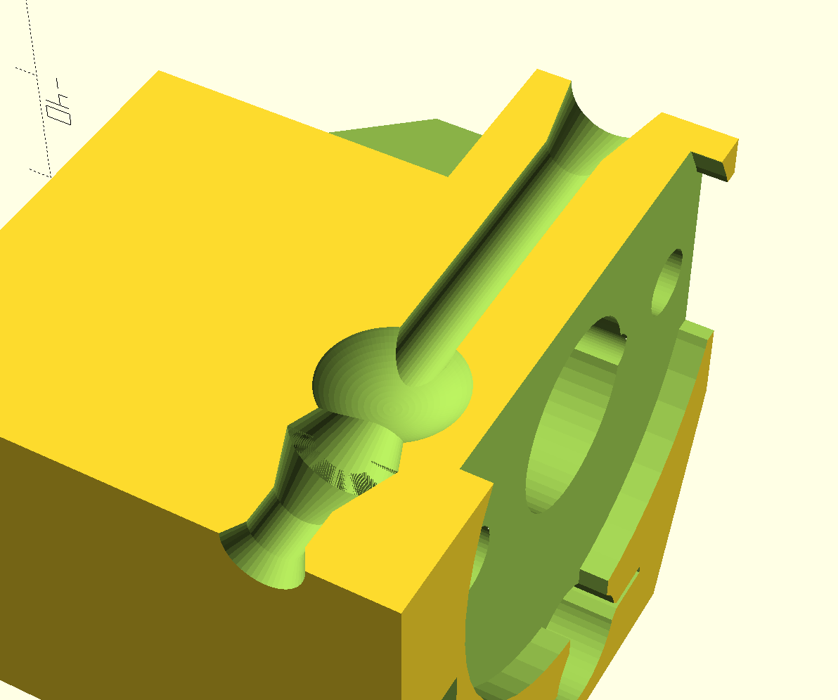
That little extension after (!) the FINDA tube? That looks like it was supposed to be in the FINDA tube.
Re: adventures in assembly, comments on building instructinos...
are you taking about the tube under where the ball sits? that acts as a drain if some junk gets in there, but usually it gets full of strings and clogs up.
they do plan to use the sensor in the future but again that sensor causes a lot of issues and they disabled it for now. there are firmware branches were it is enabled and i think on the last firmware 3.5.0 they did turn its function back on.
“One does not simply use a picture as signature on Prusa forumsâ€
Re: adventures in assembly, comments on building instructinos...
It's not much of a drain if it's a closed space... :p