spreading distance between X axis rods for more rigid extruder
I am considering working further on a design to do this modification - does anyone want to talk me out of it? Specifically I wonder if there is a known problem with moving the lower X axis rod downward. For example, would it get too hot, or would the bearing get too hot, has it already been tried? etc.
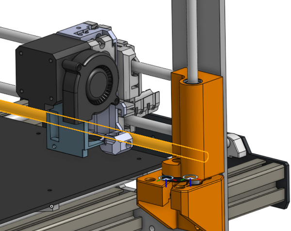
the proposed location is highlighted in this Onshape cad model in orange. The original rod locations are still there in 2 of the images, both in gray/silver color.
To change the mounting I would redesign the X axis ends to move the nut to the bottom. This also may allow for a different fan location (on the side instead of front). This will help with the R3 parts and the 'dyson' airflow modification. Obviously I would have to redesign the extruder carriage a lot and I have not done any of that work yet. The wire routing would have to change.
The primary or perhaps only benefit is that the vertical position of the nozzle would be more rigid.

Re: spreading distance between X axis rods for more rigid extruder
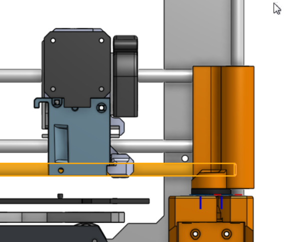
Just looking at the front on view, it looks like when you add the bearings, and a holder, that they'll sit below the nozzle.
Re: spreading distance between X axis rods for more rigid extruder
Just looking at the front on view, it looks like when you add the bearings, and a holder, that they'll sit below the nozzle.
ha! well obviously that would be quite a big fail : )
I've just patterned the linear bearing down 20mm (to match the lowest rod position) and there is room for the bearing and some material but not for the same clamp style as the original MK3 carriage. I think you are correct, the proposed position that I show is probably too dramatic of a change but rather than 20mm lower, I think I can do 15mm if I design my retention a little bit differently. I would also need to make the carriage parts from some pretty heat-resistant material.
The existing MK3 design has a pretty healthy offset between the bed and that lower bearing AND the existing design is very soft in the Z direction which anyone can see by lightly pressing down on the extruder.
Re: spreading distance between X axis rods for more rigid extruder
My thought is that this is solving a problem that doesn't exist. Let me explain.
1) The force of gravity on the extruder motor is constant. That's the heaviest part of the whole assembly. Since it exerts a constant torque on the two rods, the only possible effect is a slight rotation of the extruder assembly when it's in the middle of the X travel versus at either end. I don't have the instrumentation to measure that, but it's not visible to the naked eye.
2) The nozzle can exert a very small, but variable, upward force on the extruder assembly when it's printing, but the nozzle is only about 30mm away from the centerline of the supporting rods.
3) The largest variable force that will be encountered is from the extruder pulling filament in from the spool, because sometimes spools have a lot of friction. Again, this force is centered about 30mm away from the center of the rods.
4) From the geometry of the setup, if there is an artifact caused by (2) or (3) the nozzle will move somewhat up and away from the centerline of the rods. If there's an artifact due to (1) the nozzle will move relatively down and toward the centerline for X locations in the middle or up and away for X locations near the extremes. Have you seen defects that you can identify with either of these kinds of undesired motion?
Vibrations of the extruder assembly caused by rapid accelerations in the X direction won't be affected by moving the rods apart. That problem (which does exist, and shows up as "ghosting") would be addressed by using larger-diameter rods.
If there is no evidence of a problem, then why try to solve it?
Re: spreading distance between X axis rods for more rigid extruder
.... Have you seen defects that you can identify with either of these kinds of undesired motion?....
If there is no evidence of a problem, then why try to solve it?
Jay, thanks for taking time to write that well thought out response. I quoted part of your response as a potentially loaded question ; )
for sure, there are artifacts in this type of printing and people attribute them to all kinds of things. You may be correct in that the things I am looking at may not be the largest contributors to the problems. I am looking at other areas as well but I am not overly eager to mod my printer as it is doing quite well.
What I notice is that the extruder motor is a relatively heavy and far-overhung load. Gravity is constant, but the extruder is commanded to move up and down 'quickly' to do hop moves and the machine is always full of energy so there is a potential for vibration modes in the vertical axis.
I do NOT plan to try any plain, non rolling-element bearings but for a person who does then spreading them apart will reduce the forces on these bearings caused by the motor overhang. Reducing this force will reduce bearing loads, hence the friction load but I do agree this is a very small value when you consider the bearings in the stock design.
I think that a lot of the artifacts are caused by stepper cogging, vibrations set up by high jerk (acceleration changes), bearing seal drag and also something from the gears of the extruder and finally, from friction in the filament path. This is typical of so many problems in mechanical engineering - it's usually the friction!. : )
thanks again,
mark
Re: spreading distance between X axis rods for more rigid extruder
themzlab,
Thanks for pointing out that I forgot the acceleration of the assembly due to Z-hop.
But actually, I think this comes out to be rather insignificant.
We all know that the acceleration due to gravity is 9.8 meters per second squared. Phrased in millimeters, that is 9800 millimeters per second squared.
The default Z acceleration for the printer (which you can find out with an M503 command) is only 200 millimeters per second squared. So the machine's acceleration is 2% of the acceleration of gravity. Using the equation Force = Mass * Acceleration, that means that the force on the motor due to Z acceleration is only adding (or subtracting) 2% of the static force already present due to gravity.
In practical terms, I've watched this printer and my older printer vibrate in X and Y when printing very small infill zig-zags, but I've never seen or suspected vibration in the vertical direction.
-RJ