Re: Quieting the R3 blower design
Since these monologs aren't much fun, I think this will be my last posting.
Well, we can't have that, now can we 😉
I haven't been as active in this discussion as I'd like to, but work, a heatwave and preparations for my summer holiday has taken much of my energy lately. I have been reading along with great interest, whenever I could.
I think I never got an answer to a question I asked earlier. Whether you plan to power the board with the printer 24V, or will be using a separate (isolated) supply? In case of the first option, I don't think you can read the pwm pulses from the Einsy board. You would end up having common GND on both boards, and thus grounding the pwm out from Einsy (as it uses gnd for switching, as far as I can see).
I have been reading up on fans lately (PC fans mostly), and it seems the 3-wire fans are not supposed to be PWM regulated at all. They should rather be fed a variable DC supply, or at least the PWM should be filtered and smoothed. That could explain the noise from the fan, if it isn't built for a pwm chopped power supply.
I think I'll experiment with a completely different approach than you. I'll try to smooth the pwm output from Einsy, condition it with an opamp, and then feed a (pwm dependent) DC supply to the fan. That way one could perhaps also make it for 12V, making it easier to find a replacement fan locally.
Re: Quieting the R3 blower design
I think I never got an answer to a question I asked earlier. Whether you plan to power the board with the printer 24V, or will be using a separate (isolated) supply? In case of the first option, I don't think you can read the pwm pulses from the Einsy board. You would end up having common GND on both boards, and thus grounding the pwm out from Einsy (as it uses gnd for switching, as far as I can see).
I had planned to power the board with the printer 24v. I didn't realize there might be a problem with that approach. The testing I've done so far was with 24v from just a bench power supply. Hmmm... I guess I better test it!
It wouldn't be any problem to power a 12v fan with the design I'm using. Just replace the 5v LDO with a 12v LDO and then adjust the buck converter output to be about 15v.
Re: Quieting the R3 blower design
Since these monologs aren't much fun, I think this will be my last posting.
Well, we can't have that, now can we 😉
I haven't been as active in this discussion as I'd like to, but work, a heatwave and preparations for my summer holiday has taken much of my energy lately. I have been reading along with great interest, whenever I could.
I think I never got an answer to a question I asked earlier. Whether you plan to power the board with the printer 24V, or will be using a separate (isolated) supply? In case of the first option, I don't think you can read the pwm pulses from the Einsy board. You would end up having common GND on both boards, and thus grounding the pwm out from Einsy (as it uses gnd for switching, as far as I can see).
I have been reading up on fans lately (PC fans mostly), and it seems the 3-wire fans are not supposed to be PWM regulated at all. They should rather be fed a variable DC supply, or at least the PWM should be filtered and smoothed. That could explain the noise from the fan, if it isn't built for a pwm chopped power supply.
I think I'll experiment with a completely different approach than you. I'll try to smooth the pwm output from Einsy, condition it with an opamp, and then feed a (pwm dependent) DC supply to the fan. That way one could perhaps also make it for 12V, making it easier to find a replacement fan locally.
I had planned to power the board with the printer 24v. I didn't realize there might be a problem with that approach. The testing I've done so far was with 24v from just a bench power supply. Hmmm... I guess I better test it!
It wouldn't be any problem to power a 12v fan with the design I'm using. Just replace the 5v LDO with a 12v LDO and then adjust the buck converter output to be about 15v.
But wait... In my testing, I had the Prusa power supply power the Prusa I3 Mk3, and I had a separate 24v lab power supply power the Arduino circuit. However, they both shared a common DC ground. So, if there were to be a problem, wouldn't it have surfaced already?
Re: Quieting the R3 blower design
I had planned to power the board with the printer 24v. I didn't realize there might be a problem with that approach.
There isn't a problem as such. You just need a minor change.
You are taking the 5V from the Einsy fan output and routing it to an input on your Arduino in order to read the pwm signal. But the Einsy board regulates the fan on the gnd pin, not 5V.
But wait... In my testing, I had the Prusa power supply power the Prusa I3 Mk3, and I had a separate 24v lab power supply power the Arduino circuit. However, they both shared a common DC ground. So, if there were to be a problem, wouldn't it have surfaced already?
But did they share common ground? If you connected the two through the fan output from Einsy, that ground isn't ground, but pwm. Perhaps that explains the weird and noisy scope screenshots of the tacho output?
Re: Quieting the R3 blower design
So, if I'm understanding what you mean, it sounds as though I should instead be sampling the fan GND as compared to actual GND instead of what I'm doing now, which is sampling the fan's 5v line as compared to the fan GND. Is that right?
Re: Quieting the R3 blower design
Exactly.
It didn't matter much when you had separate supplies, but hooking it all up to a common supply, and thus real common ground, that is where it will make a difference whether it works or not.
Re: Quieting the R3 blower design
Exactly.
It didn't matter much when you had separate supplies, but hooking it all up to a common supply, and thus real common ground, that is where it will make a difference whether it works or not.
I just now did the measurement, and you are correct. If the fan isn't running, then fan GND is 3.3v higher than actual ground. If I set the fan speed to 12 (out of a possible 255), then the o-scope shot of fan GND relative to actual GND is:

On the other hand, if I set fan speed to 230, the picture is:

So, as you can see, in some sense the PWM pulses are inverted.
Thanks for pointing this out!
Re: Quieting the R3 blower design
Exactly.
It didn't matter much when you had separate supplies, but hooking it all up to a common supply, and thus real common ground, that is where it will make a difference whether it works or not.
Unfortunately, as hinted at above, as the fan setting gets higher and higher, it looks less and less like a true PWM signal. Here it is at fan speed 245:

i..e. at the higher speeds it's not even a digital signal anymore without some kind of further processing done on it. The question is: what kind of processing?
It would appear that at the higher speeds, the Prusa I3 MK3 doesn't deliver a proper PWM signal.
[Edit: Rather than splitting hairs, the simplest (probably not the best) answer would be to say that either any fan speed beyond 85% is the same as 100%, or, similarly, any fanspeed beyond 85% is just 85%. i.e. comperss the entire upper 15% of the range into one speed. Not having much experience with the R3 design, it's hard to know whether such a blunt decision would matter or not. At least so far, based mostly on Martin Wolf's observations, In most cases, it's looking like the R3 fan design will be operated at less than 50% of its potential speed anyway.
Martin, what do you think? Is it worth preserving the resolution at the upper 15% of the range?]
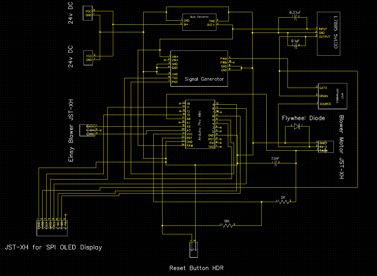
Meanwhile, here is the revised schematic:
Re: Quieting the R3 blower design
Unfortunately, as hinted at above, as the fan setting gets higher and higher, it looks less and less like a true PWM signal. Here it is at fan speed 245:
i..e. at the higher speeds it's not even a digital signal anymore without some kind of further processing done on it. The question is: what kind of processing?
I'd say it is due to lack of a proper pull-up resistor on the PWM line. There is only a little LED on the Einsy board.
Try a 1 Kohm resistor between +5V and GND on the fan out plug of the Einsy. Or another value in that ballpark, if you don't have exactly 1K at hand.
1K pullup resistor was still too much at the higher speeds to get a good signal. Reducing it to 200 ohms, then dialing in 240 fan speed on the Prusa spinner knob yielded:

which looks good.
Dialing in 245 speed with the same pullup gives:

which may be marginal, kinda in no-man's land
But dialing in 250 speed with the same pullup gives:

i.e. no visible signal left. Should I use an even lower pullup? If so, what value?
Re: Quieting the R3 blower design
At 5V and assuming a standard 1/4 W resistor, you should be able to go down to 100 Ohms. But I think we are more or less reacing the limit of how fast the output FET can switch in its current setup. Improving further on this will require hardware changes to the Einsy board. A step that I am not sure I would like to take.
I can't see the need for fine fan regulation near the max speed, as you mentioned earlier. I am inclined to say that it is good enough as it is now, with an appropriate pullup.
Good to hear, because I think I'm ready to wrap this up soon. I just finished etching a two sided PCB to instantiate the latest schematic, and I must say a two sided PCB is definitely more than twice the hassle of a single sided PCB. For instance, I'll have to manually solder 16 via holes using wire to make the connection on both sides. That's 32 soldered joints for just the via holes alone!
Fortunately, all the mounting holes align with the standoffs of the enclosure:
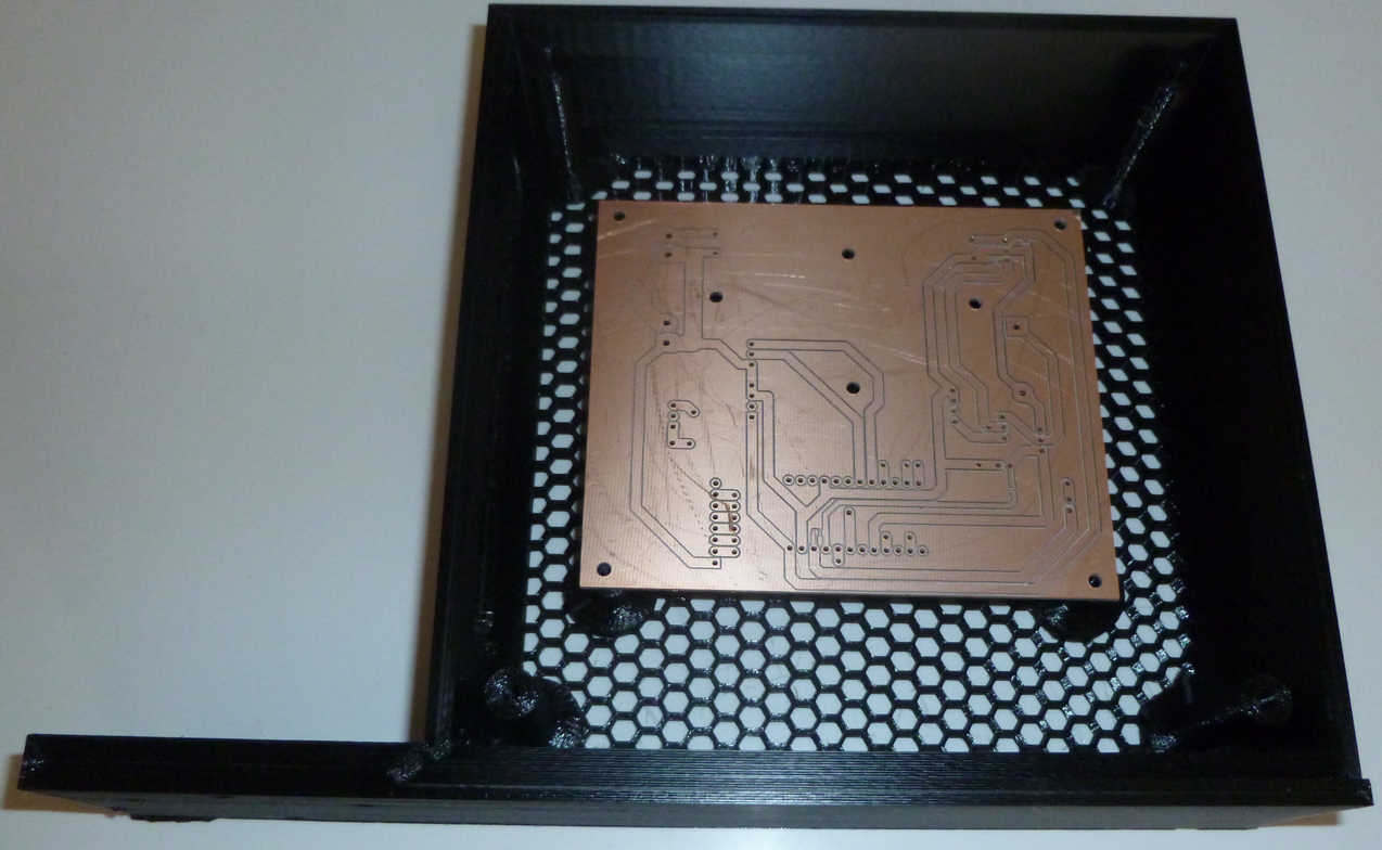
If all goes well, I'll bodge on the 100 ohm pull-up resistor and call it done. 😀
Re: Quieting the R3 blower design
Somewhat ironically, presently the pro mini won't be able to tell the difference between too high a duty cycle to read and a duty cycle of zero (fan off). So, if it fails to read a duty cycle fromthe Einsy, it will be turning off the fan.
Well, no biggie. Just something to be aware of.
Re: Quieting the R3 blower design
Good news! Using a 100 ohm pull-up resistor, the Pro Mini can read Prusa I3 MK3 fan speeds all the way up to 243 (out of 255). Now, it turns out that fan speed 243 is actually 99% duty cycle, well, at least the way the Prusa I3 MK3 has implemented it. So, at fan speed 244, the Pro Mini fails to find a duty cycle and defaults to 100% duty cycle, which works more or less perfectly in this situation. i.e. , the Pro Mini is able to read a full range from 0% to 100% duty cycle by samping the Einsy blower motor GND pin. 😀 😀 😀
Re: Quieting the R3 blower design
Oh wow. That sounds almost too good to be true 😆
I have worked a bit on my pwm-to-analog voltage idea, and i have a first draft on paper. Next step will be to get some parts and build the circuit to see if it'll work in reality.
Re: Quieting the R3 blower design
Please do post as you make progress. I'll be interested in what you come up with.
I'm nearly finished with version 1.0. You can see where I bodged on the 100 ohm resistor:
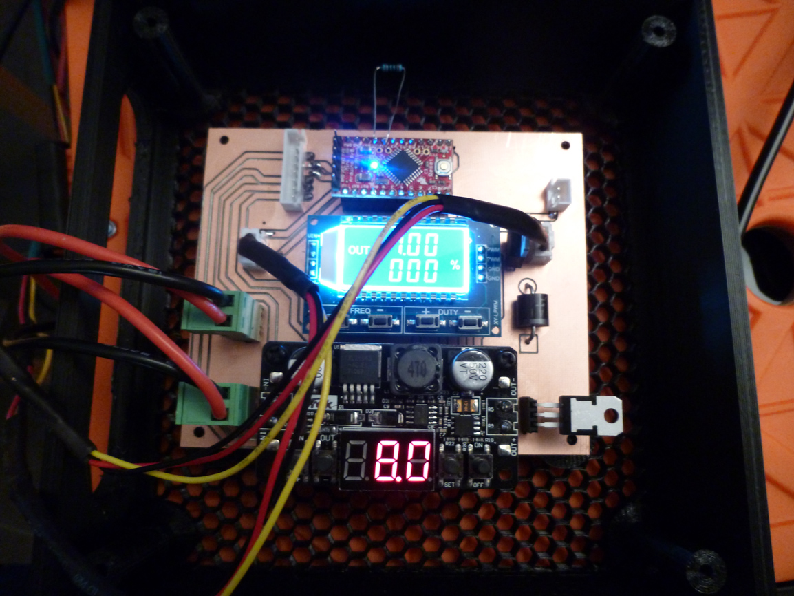
I have to re-do the project box, though, because the PCB standoffs turned out to be a bit too high. I have that printing now.
Version 2.0 will add the OLED and reset button whose JST-XH connectors are already on the PCB, waiting to be connected.
At that point the hardware will be finished.
Then, Version 3.0 will be a software upgrade, where in gcode I specify RPM (as a percentage of max RPM), rather than PWM' speed, as is presently the case. Also, I'll monitor total print time and display that on the OLED so that it doesn't disappear at the end like it does with the Prusa firmware.
Re: Quieting the R3 blower design
You really go all-in to make that fan quiet. I am impressed.
Please do post as you make progress. I'll be interested in what you come up with.
Of course.
Right now it is still just at the pen-and paper stage, but my idea goes something like this:
The PWM out from Einsy gets low pass filtered with a simple first order RC filter. Then the voltage gets further low pass filtered and inverted with an opamp. In principle that is all is needed. In reality, I don't think I'll find an opamp with rail-to-rail inputs and output, 5V supply and enough output drive to supply the fan directly. I will most likely need a higher supply voltage and an output booster.
But first I need to upgrade my printer with the R3 parts. While I do that, I will also characterise the fan for its pwm-to-rpm and voltage-to-rpm relationships. Hopefully the fan responds relatively linear to voltage changes. After that is done, I should be able to calculate filter resistor and capacitor values.
Re: Quieting the R3 blower design
You really go all-in to make that fan quiet. I am impressed.
Please do post as you make progress. I'll be interested in what you come up with.
Of course.
Right now it is still just at the pen-and paper stage, but my idea goes something like this:
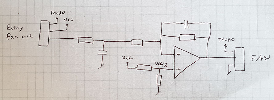
pwm-to-voltage.jpg
The PWM out from Einsy gets low pass filtered with a simple first order RC filter. Then the voltage gets further low pass filtered and inverted with an opamp. In principle that is all is needed. In reality, I don't think I'll find an opamp with rail-to-rail inputs and output, 5V supply and enough output drive to supply the fan directly. I will most likely need a higher supply voltage and an output booster.
But first I need to upgrade my printer with the R3 parts. While I do that, I will also characterise the fan for its pwm-to-rpm and voltage-to-rpm relationships. Hopefully the fan responds relatively linear to voltage changes. After that is done, I should be able to calculate filter resistor and capacitor values.
So, you're keeping the same PWM frequency as what the Prusa I3 MK3 is already using? Wouldn't it still be audibly noisy then? Or, are you doing it for different reasons?
Re: Quieting the R3 blower design
So, you're keeping the same PWM frequency as what the Prusa I3 MK3 is already using? Wouldn't it still be audibly noisy then? Or, are you doing it for different reasons?
I am doing it for the noise. The PWM frequency should disappear, and leave behind an averaged DC voltage that is proportional to the PWM duty cycle.
Re: Quieting the R3 blower design
From what I have read, straight d.c. voltage may stall at low rpm's that pwm may not stall at.