RE: Old LCD board modification to allow fw 3.9.0 brightness control ?
That's a good point, if that is not wired right then it will not work
RE: Old LCD board modification to allow fw 3.9.0 brightness control ?
@vintagepc
I haven't swapped cables yet but will do so after work tonight.
RE: Old LCD board modification to allow fw 3.9.0 brightness control ?
@chris-e
I just opened the Einsy door and yes I do have the daughter board for the LCD cable connections.
Very interesting if this is the cause, given Prusa only mention you need a display board from 2nd half last year.
Did Prusa themselves say it won't work with the daughter board or have you heard of any mods or work around?
RE: Old LCD board modification to allow fw 3.9.0 brightness control ?
@steve-j
I have only seen it mentioned here: https://github.com/prusa3d/Prusa-Firmware/pull/2270#issuecomment-542837281
Not heard of a work around either unfortunately.
RE: Old LCD board modification to allow fw 3.9.0 brightness control ?
There won't be one in that case as the pin is bound to something else. You'd need to update the Einsy board.
RE: Old LCD board modification to allow fw 3.9.0 brightness control ?
As I wanted to upgrade to the Brightness control as well, I've also thought I will also upgrade my MK3S to the Midas LCD in one step.
The LCD modification worked fine (please note, it's not fully PIN compatible, as Brigthness + and LCD V0 isn't the same. Midas needs negative voltage for the LCD contrast L0 voltage, which is the same PIN 15 on LCD).
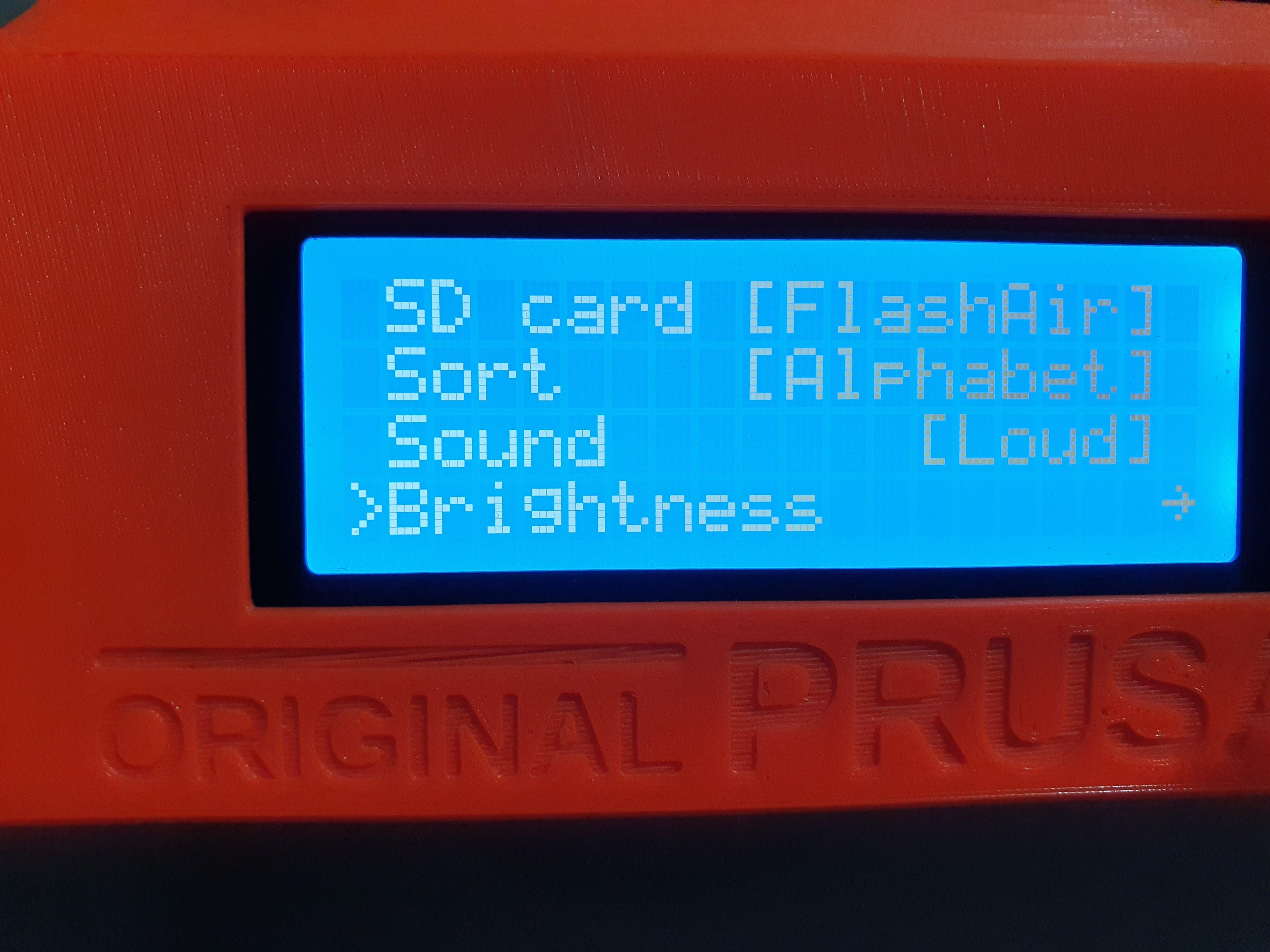
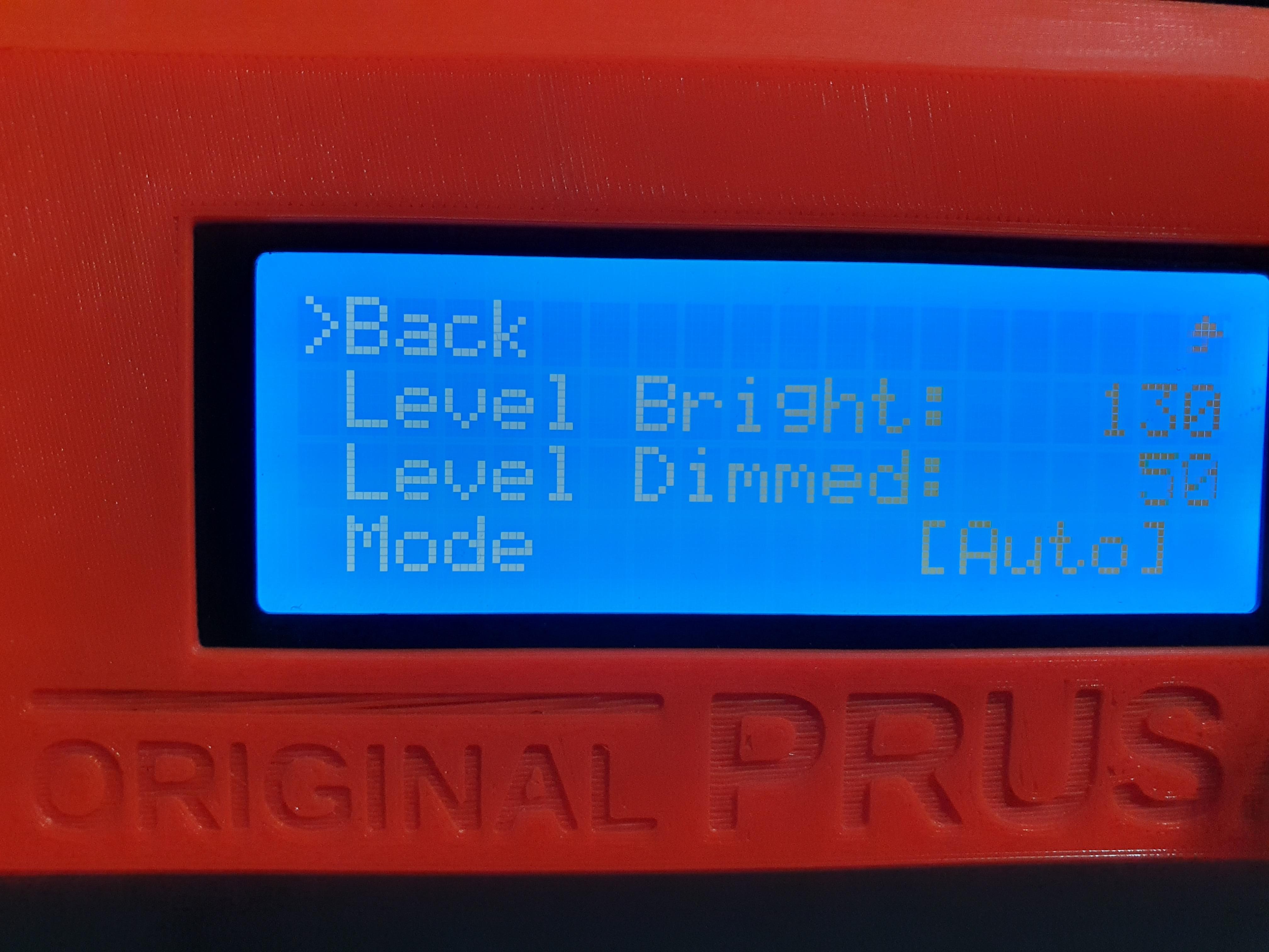
Unfortunately, I also not got the Brithtness control Menu entry. So I checked the Firmware and the Einsy Schematic further:
And I can confirm, if you have an einsy board version lower or equal <= v1.0a, you have a daugther board (so called ERBB addon board - Einsy Rambo Buffer Board), which contains the additional 2MB of flash ram. The new Einsy boards already has this 2MB Flash on board itself since version 1.1a.
As this daugther board uses at the LCD P2 connector PIN 1 for the flash module communication (nCS negative Chip Select over 74LVC125 A3 input PIN) the same PIN, as the LCD P2 connector on newer boards uses for the LCD brightness control, it's not possible to use brightness control for older Einsy boards OOB.. also if you have a newer LCD module.
The brightness control uses the Atmega2560 PIN 5 output (PE3). But older Einsy boards, don't have this PIN connected to the boards at all.
I will try, to probably solder a cable on the PIN on the old Einsy board, and bring it to the LCD Module directly, for the brigthness control 🙂
RE: Old LCD board modification to allow fw 3.9.0 brightness control ?
@neudy
Thanks for the explanation.
Perhaps Prusa would be best letting people know that to get the dimming feature with the new firmware, it's not just a matter of having a later display board, but there is also a version of the Einsy board as well that is required.
Let us know if you have any success with the mod you are proposing to try. 🙂
RE: Old LCD board modification to allow fw 3.9.0 brightness control ?
@steve-j and all others:
Yes! I finally achieved to get the old einsy board 1.0a working, with a modification and the new LCD board 🙂
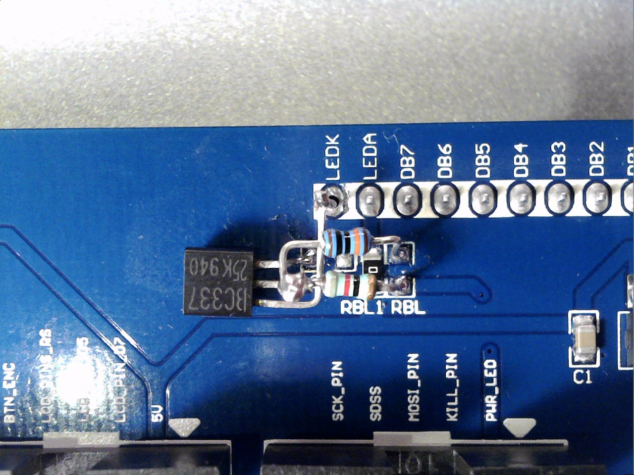
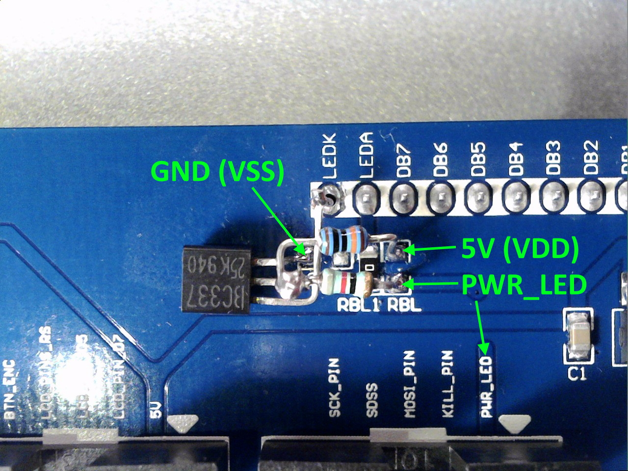
As mentioned, I've lifted the PIN 5 (PE3) of the Atmega2650 and soldered a copper-wire on it (0.5mm dia). Then I added it to a 120Ohm resistor and soldered the other side of the resistor to the ERBB board, P2 - PIN 1, which is facing towards the LCD cable. That's it! After turning on the MK3S with the 3.9.0. FW, the Brightness menu was visible and working fine 🙂


RE: Old LCD board modification to allow fw 3.9.0 brightness control ?
@neudy
The close up shot makes it look like you are using a poker from the coal fire to attach a massive cable to the poor little Atmega chip! Lol...
well done,
I don't think it is something I would attempt..., My old hands are not steady enough.!
regards Joan
I try to make safe suggestions,You should understand the context and ensure you are happy that they are safe before attempting to apply my suggestions, what you do, is YOUR responsibility.Location Halifax UK
RE: Old LCD board modification to allow fw 3.9.0 brightness control ?
@neudy
Neudy, great work.........thanks for working this out for us. 🙂
I have a friend who is a trained electronics technician so I am hoping that he will be able to do the soldering for me to mod my Einsy board.
When you say you "lifted" the pin 5, did you mean you had to release this pin's connection to the board and then solder the wire to it, or can the pin stay connected to the Einsy when the copper wire is attached? (I'm not experienced in electronics at all and don't follow in relation to this step.)
RE: Old LCD board modification to allow fw 3.9.0 brightness control ?
@joantabb
indeed, from the picture it looks scary 😆 And of course, I would no one recommend doing this like this, unless you are aware, you can fully damage your board and you aware of the risks. I would recommened, to buy a newer version of the Einsy board.
@steve-j
You don't need to lift up the Pin, as it's nowhere connected to the board at all. But for me, it was easier to solder the wire on it. If you are more experienced, and you have better wire, you can also solder it directly on the boards side.
But as told to @joantabb, I would not recommend anyone to do it the same way, unless you aware of the risks. It's easier to buy a new Einsy board with a higher version 🙂
But at least, it's proven, it's possible to do it also with the older board versions, with risky modification 😜
I'm looking forward to your results and stay healthy!
RE: Old LCD board modification to allow fw 3.9.0 brightness control ?
@neudy
Hi Neudy,
Can I please confirm the value of the required resistor for between the Atmega pin and the ERBB board?
Is it 120 Ohm as per your post or 120K Ohm which I know is somewhere in the required circuity as per other posts above. I just want to double check before I get the parts together - my mate says the soldering will be easy so I want to give this a try. 🙂
RE: Old LCD board modification to allow fw 3.9.0 brightness control ?
@vintagepc
@neudy
Just wanted to thank you guys for your help with this.
Looks like I might end up with a dimmable solution and have learnt a little along the way.
RE: Old LCD board modification to allow fw 3.9.0 brightness control ?
@steve-j
It's a simple 120 Ohm resistor. As I only had a 100 ohm one, I've use a lower one.
But regarding the Einsy 1.1b schematic, there is a 120 ohm in line.
Happy to hear, you resolved it and you also ended up in a Dimmable version now 🙂
RE: Old LCD board modification to allow fw 3.9.0 brightness control ?
@neudy
Thanks for confirming the resistor rating.
I haven't done my mod yet....just getting things ready......but I'm very hopeful that it will work. 🙂
RE: Old LCD board modification to allow fw 3.9.0 brightness control ?
@vintagepc
@neudy
Success 🙂
My mate has done the Einsy mod for me and it works a treat.
Again, thank you both for your help.....appreciate it.
RE: Old LCD board modification to allow fw 3.9.0 brightness control ?
@vintagepc
@neudy
Looks like I celebrated too early.
Trying a print just now, firmware is reporting errors and whilst the bed and extruder would start to heat up very slowly on the first attempt, before it stopped with an error only about half way through the required temp, when I try now I am getting no power at all to the extruder or bed.
Power supply voltages to the board are good, thermistors give a reading and the printer will boot up but I'd suggest perhaps a bit of damage was done to the board during the mod. My mate did have some issues and had to clean out some tracks between the pins so perhaps too much heat has somehow caused problems with the ATmega chip or surrounding components.
Anyway, it's a good excuse to upgrade to the MK3S current board 🙂
Before I do though, what else could I check? I have gone back to the latest 3.8.1 FW but still problems.
RE: Old LCD board modification to allow fw 3.9.0 brightness control ?
Hi, after successful upgrade of my filament sensor (rev 01 to 04 by adding resistor and diode) I am trying to do this. Because I have A003 LCD.
No idea why, but it is not working for me - yet. But I get PWM signal on PWR_LED pin (0,8V), so my issue is probably just in Transistor.
In original github post there is "6DW", so I want to share this with you: according http://www.s-manuals.com/smd/6d it should be BC817.
RE: Old LCD board modification to allow fw 3.9.0 brightness control ?
I poked at this a bit, should be possible but you will need to alter the board. I believe the following will work, but have not tested yet. Plan to try it at some point.
-Need 100 0hm resistor, 100k pullup, general purpose NPN transistor.
- Will need to cut LEDK trace or remove the pin from the LCD connection as it's grounded in the 003 board.
- 100ohm goes from E2 P1 to base of transistor. 100K acts as a pullup resistor to + 5v
-Transistor emitter to ground
-Transistor collector to LED_K on LCD module, after removing pin to backplane board.
Oh man, thanks for breaking it down. Can confirm what you wrote works!
Instead of cutting up LEDK track, I pulled out the header leg by applying a bit of solder and pulling it with pliers. I then fed a 30AWG wire down the hole and soldered it to the LEDK pad on the other side. Also it's possible to make all the required components (NPN, 100R, & 100K) compact around the LEDK pad, but this requires you to carefully bend some legs
www.antalife.com
RE: Old LCD board modification to allow fw 3.9.0 brightness control ?
@steve-j
I'm sorry for the delayed reply. I'm sorry, to hear, you are facing issues, after the mod. My printer is printing fine, without any issues so far.
After you mentioned, it heated up slowly and now it's not heating up at all, please check the fuses on the Einsy. Maybe you created during the mod a short circuit, which damaged the fuses now.
I hope you will find your issue and you will finally get a brigthness control fully working for you as well 🙂