RE: Old LCD board modification to allow fw 3.9.0 brightness control ?
I unsassembled my display so I could get a good picture of my board:
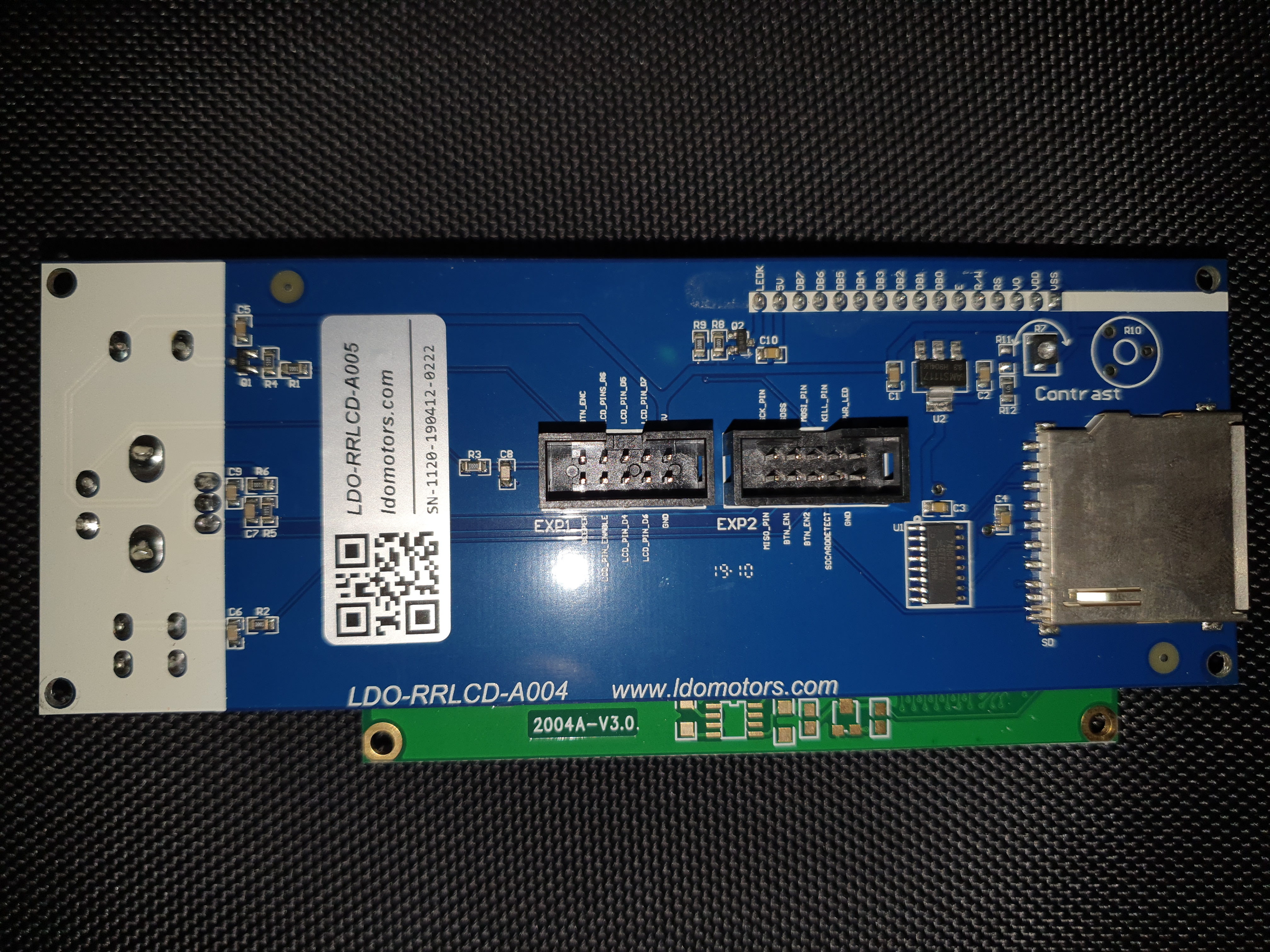
From what I am reading, this version should support the new dimming functionality, so I don't know why it won't work.
RE: Old LCD board modification to allow fw 3.9.0 brightness control ?
Looks like the parts are there. That said, if the system isn't offering the brightness menu, then it's not seeing the 5v that should be on the PWR_LED pin when brightness control is enabled. So either the pullup resistor is not working, it's grounded elsewhere, or there's a cabling issue.
RE: Old LCD board modification to allow fw 3.9.0 brightness control ?
@vintagepc
Thanks for your help with this - really appreciate it.
I know nothing about electronics but do have a multimeter 🙂
Are there any tests you can suggest that might help me to troubleshoot?
RE: Old LCD board modification to allow fw 3.9.0 brightness control ?
Sure... If you can find a way to measure the voltage at PWR_LED when the unit is on and attached, that might provide some insight.
RE: Old LCD board modification to allow fw 3.9.0 brightness control ?
@vintagepc
Thanks for your contribution. That saves my old A003 board.
Statt zu klagen, dass wir nicht alles haben, was wir wollen, sollten wir lieber dankbar sein, dass wir nicht alles bekommen, was wir verdienen.
RE: Old LCD board modification to allow fw 3.9.0 brightness control ?
@vintagepc
If I take a voltage measurement across the PWR_LED and GND pins of EXP2 connector, I am only getting about 0.77 volts.
Are these the 2 pins I should be measuring?
RE: Old LCD board modification to allow fw 3.9.0 brightness control ?
Yes, that's the points I mentioned. But just to clarify - are you measuring with the display connected or did you just take a measurement at the ends of the cables? That will make a difference.
If the display was connected, put your meter in Ohms mode, disconnect the display and measure across R8 and R9 (one at a time) in that little cluster of components next to the LEDK pin.
R9 should measure about 100 ohms, R8 about 100Kohms
RE: Old LCD board modification to allow fw 3.9.0 brightness control ?
@vintagepc
Good evening.
I have some resistance measurements for R8 and R9.
I have never measured resistance before but from my research, I think I have worked it out........
Bear in mind my multimeter is only a cheapie.
For R8, I have a value of 95.4 using the multimeter scale of 200K, so I understand I have resistance here of 95.4Kohms
For R9, using the 200 scale, I have a value of 100.1 which would indicate resistance of 100.1 ohms.
Hopefully I have interpreted things correctly.
RE: Old LCD board modification to allow fw 3.9.0 brightness control ?
Hm, those seem reasonable. Let's take a few more measurements to confirm but it's starting to look like something with the cable or the Einsy. (Now would be a good time to double check you really do have the 3.9.0 RC installed...)
Back to voltage mode, with the display connected and printer on, what do you measure from each of the sides of R8 and 9 to ground? (4 measurements total)
RE: Old LCD board modification to allow fw 3.9.0 brightness control ?
@vintagepc
Evening,
I definitely have 3.9.0 installed.
I reinstalled the firmware with the MK3S file selection - assume the fact that I'm running the MMU2S makes no difference.
In relation to the voltage readings, I'm having trouble getting any reading but think maybe I'm not grounding the multimeter properly. Where am I best to place the negative probe to get a reading?
RE: Old LCD board modification to allow fw 3.9.0 brightness control ?
@vintagepc
I also took a measurement with the display unplugged and power on, from pins 1 @ 2 of connector 2 - ie PWR_LED & GND.
I have a reading of just under 5 volts coming from the Einsy.
RE: Old LCD board modification to allow fw 3.9.0 brightness control ?
I believe the metal shell of the SD card holder is grounded.
RE: Old LCD board modification to allow fw 3.9.0 brightness control ?
@vintagepc
Thanks again for your help with this......
OK, readings as requested:
Across R8, voltage is 5.0 V on the side facing the cable connectors and 0.72 V on the board edge side.
Across R9, voltage is 0.76 V on the connectors side and 0.72V on the board edge side.
RE: Old LCD board modification to allow fw 3.9.0 brightness control ?
Hmm... the readings would agree with a situation where the transistor (Q2) is shorted.
Does your meter have a diode test mode? Remove the LCD from the printer and follow this guide to test it:
https://vetco.net/blog/test-a-transistor-with-a-multimeter/2017-05-04-12-25-37-07
The solo pin is the collector,
Pin closest to the connector is the emitter
remaining pin is the base.
The transistor is an NPN type.
RE: Old LCD board modification to allow fw 3.9.0 brightness control ?
@vintagepc
Evening,
Sorry, I haven't had the chance to respond sooner....
I used the diode testing setting of my cheap multimeter ( ->+ ) and have some readings, but don't know what these indicate:
Base to emitter returns a value of 698
Base to collector returns a value of 695
Emitter to base gives me nothing - the multimeter with probes not touching anything says "1" and when I connect to these 2 pins also says "1". (If I touch the probes together in this made, value will eventually show "001".
The multimeter will never show "OL".
I haven't got a clue what these readings indicate in relation to the state of the transistor.
RE: Old LCD board modification to allow fw 3.9.0 brightness control ?
@vintagepc
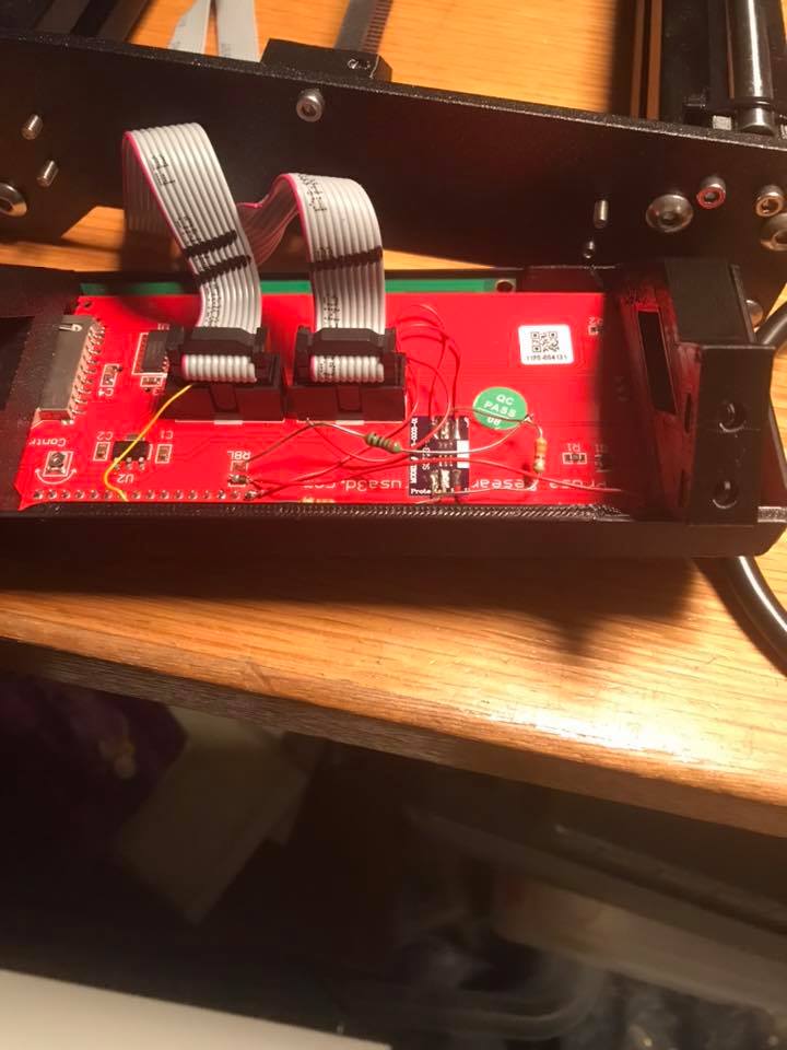
I have also found my earlier display that I forgot I had.
It is this exact version that someone has already modified to get the dimming to work with the new firmware.
Only problem is, I don't know what parts are involved and can't follow the wiring.
I'd like to get this older display working if an easy mod and will leave my newer display unaltered.
Is it likely that I will still only need the 2 resistors and the transistor to mod this old board?
RE: Old LCD board modification to allow fw 3.9.0 brightness control ?
Sorry for the delayed reply. I must have missed the notification on your first message.
The transistor seems to be OK according to your measurements so far. The normal forward voltage of a junction is ~0.6v. (e.g. 600 on the meter in diode mode) Did you also check collector to base and collector to emitter?
I can't really see much from the picture of the second board. In any case, I'm not familiar enough with that part to comment on it. Is there any more detail at the location you found that photo?
RE: Old LCD board modification to allow fw 3.9.0 brightness control ?
@vintagepc
I purchased a decent multimeter and have rechecked the transistor:
Base to emitter = 666
Base to collector = 663
Emitter to base = OL
Collector to base = OL
Collector to emitter = OL
Emitter to collector = OL
From what you have been asking me to check, am I right to think that board components are acting as they should, in which case I'm wondering why the new firmware won't recognise these components and allow the dimming setting menu to be displayed.
The only thing I haven't done is replace the cables to the display, but I do not have any of these spare to check.
Could it per chance have anything to do with Octoprint or the MMU2 setup that I am running?
RE: Old LCD board modification to allow fw 3.9.0 brightness control ?
Did you try swapping the two cables as I suggested? That should identify or resolve any cabling issues
e.g. put the P1 cable in the P2 socket on *both* ends, and vice versa.
This should all be independent of octoprint or the MMU2.
RE: Old LCD board modification to allow fw 3.9.0 brightness control ?
@steve-j
Does your Einsy have the additional daughter board that the LCD cables connect to? I couldn't get the menu to show and that was apparently the cause of it.