Enabling Auto Leveling in Firmware
I just bought an inductive proximity sensor for my Prusa i3 to do auto leveling. However, I'm not sure about how to activate auto leveling in the firmware. I've read up on how to enable auto leveling by editing the Marlin firmware, but is there a way to enable it without overwriting the firmware settings from the 2.2.1.HEX file? Is my option to overwrite with the general Marlin FW?
Re: Enabling Auto Leveling in Firmware
Hi Nathan
As far as I can tell, the first step is to edit the file configuration.h and uncomment the following line:
//#define ENABLE_AUTO_BED_LEVELING
There are also instructions following that line.
You will of course, need to obtain the firmware source code and recompile/upload as necessary. You will always be able to revert to the original hex file (unless you manage to somehow damage the RAMBo bootloader).
Peter
Please note: I do not have any affiliation with Prusa Research. Any advices given are offered in good faith. It is your responsibility to ensure that by following my advice you do not suffer or cause injury, damage…
Re: Enabling Auto Leveling in Firmware
Sorry, should have added that you may not have much luck with "auto bed levelling". From what I can make out, it doesn't level the bed; it alters the Z axis to accommodate non-level beds in real-time. Therein lies the problem. The Z axis relies on gravity to work and depending on build, gravity may not be sufficient.
Peter
Please note: I do not have any affiliation with Prusa Research. Any advices given are offered in good faith. It is your responsibility to ensure that by following my advice you do not suffer or cause injury, damage…
Re: Enabling Auto Leveling in Firmware
No..."auto-bed leveling" is a misnomer as it doesn't actually level the bed. Z-height compensation leveling or auto-bed tramming might be better terms...but everyone calls it auto-bed leveling. This is a technique most new printers are using and when properly set up it really works beautifully. It would be nice if the Prusa i3 had this built in...it's not costly, the inductive proximity sensor set me back a whole $3 USD. Manually tweaking the bed or doing calibration prints all the time is a real pain...this technique eliminates that and is especially valuable for larger prints.
I figured out how to make the necessary modifications to the Marlin FW using Arduino IDE (if anyone interested start here). I had to use the v. 2.2 FW from this site as the non-compiled files where not uploaded for the newest one. Tom has a very good tutorial on youtube that offers a step-by-step walkthrough for setting up the sensor: Setting up auto bed tramming leveling tilt compensation!. So, I am all set up...just need to get the 15k and 10k ohm resistors so I don't fry my Rambo. I will post my results tomorrow 😀
Re: Enabling Auto Leveling in Firmware
awesome, I too am looking to do this, that is once I get the printer to work properly, I have already made a stl file to mount my sensor as well as fix the y axis end stop. could you post pics of your wiring of the sensor, ive watched tom's video but I just want to make sure since I couldn't find a wright up for the auto bed with Rambo 1.3... please keep updated, maybe even a video!
Re: Enabling Auto Leveling in Firmware
Ok...I took off my z-end stop and soldered the 10k and 15k ohm resistors in the appropriate configuration so the sensor is receiving 12v in, but the Rambo is only getting 5v back at the end stop. Did a test run and it works great!! Other than the small bit of soldering required this is a relatively simple hack (not to mention cheap!, total cost < $5). The benefits are just huge. The only issue really is the glass build plate. For the inductive sensor to work it has to have an inductive material to detect and that means metal. Unfortunately, these sensors are not very powerful and need to be fairly close (within a few millimeters) to the inductive surface in order to work. That rules out putting aluminum underneath the glass. Thin glass and a more ferrous metal such as a thin sheet of steel might work...but I don't want to go for thin glass. My workaround is to use small pieces of aluminum tape on the surface of the farthest edges of the glass build plate...this allows for the most conservation of build space and the sensor has no problem detecting the aluminum tape at a range of about 2.5mm. I will probably upgrade my glass build plate in the future to a PrintinZ zebra plate which has an inductive copper layer under its tack surfaces for these sensors. I've never used one before, but they have been getting good reviews and it would be nice to do away with hairspray/glue stick.
For anyone interested in doing this, I again recommend Tom's guide from my previous post. @ bryan.b, here is a basic outline of what I did:
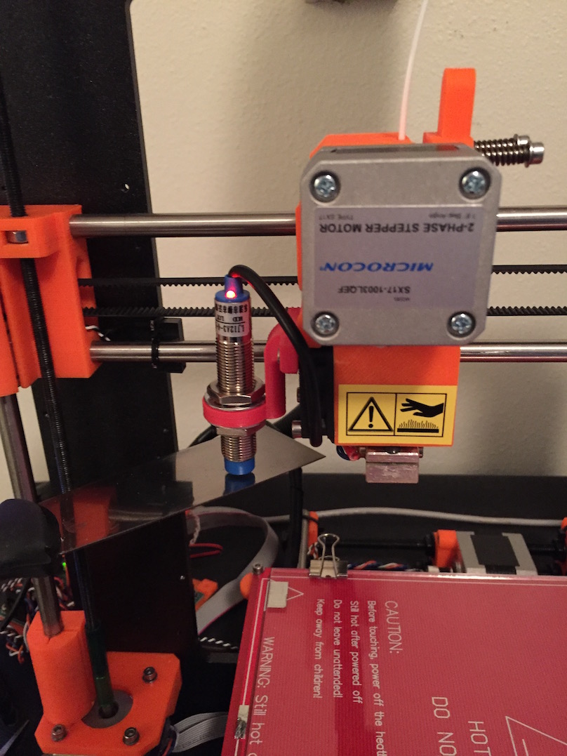
For a sensor mount I used this model off of thingiverse http://www.thingiverse.com/thing:845610 . It attaches perfectly on the top two bolts of the E3D cooling fan (really don't see a much better place for the sensor to go, but I'm interested to see other set ups or ideas).

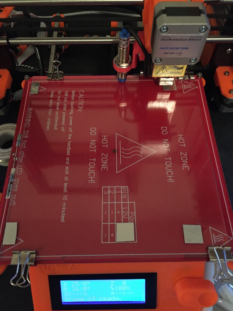
Here is what my glass build plate looks like. You can place the aluminum tape anywhere you want, but the farthest corners make the most sense...(note the travel limits of the x-axis prevent the sensor from being able to reach the actual corner on the right side, so I got as close as I could)
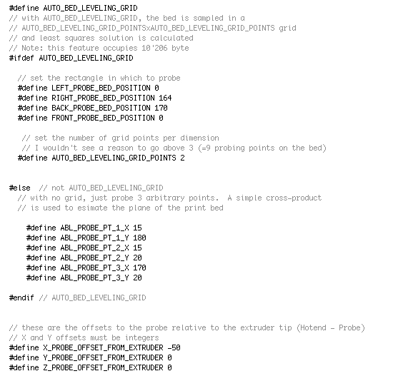
This is what my grid points look like in config.h:
Continued...
Re: Enabling Auto Leveling in Firmware
When you enable auto-bed leveling the G28 homing function will home Z at the center of the build plate...since i'm using a glass plate and don't want to have a piece of aluminum tape in the center of my build space I had to modify the z_safe_homing code in config.h. By changing the z_safe_homing_Y_point to /10000 instead of /2, it will home to the x center, but keep the y at zero. Then just put a bit of tape at the top center of the build plate and no crashy crashy, breaky breaky.

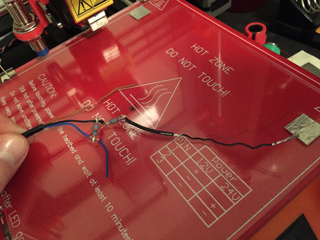
Wiring for the sensor is pretty easy, here is a basic diagram:

After a few minutes of (ugly, but functional) soldering...

continued...
Re: Enabling Auto Leveling in Firmware
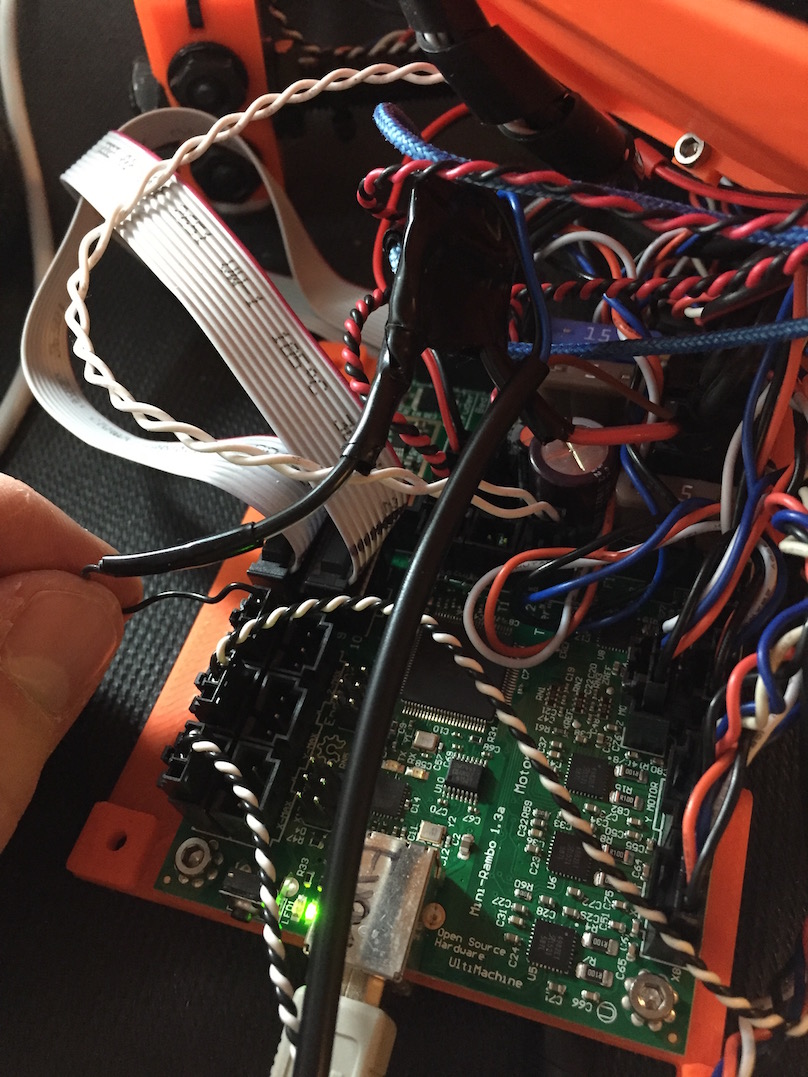
You need to connect the black wire from the proximity sensor to the z-endstop...I removed the wires from the pin header connector on the mechanical end stop and soldered it to the black wire on the sensor...make sure you put the wire in the right location when you put it back in the connector.

I know you can't really see much in this photo, but it's all connected...
continued...
Re: Enabling Auto Leveling in Firmware
A quick test to make sure it's working...just turn on the bot and put some metal under the sensor.
And the finale...
Re: Enabling Auto Leveling in Firmware
Couple questions...
1. Is there no way to mount the probe closer to the extruder nozzle?
2. Do you need to use such large pieces of tape? It looks like you have lost a good 20mm build area all around.
3. Why did you go with this probe instead of the switch that flips down?
I have been looking to do this myself but haven't had the time.
Thanks.
Re: Enabling Auto Leveling in Firmware
@richard.i
I suppose you could mount the probe closer to the nozzle, but you don't want it too close obviously. My choice was based on convenience as I found a part that fit perfectly in that location with no modification. There really aren't many places for the probe to go where it or it's cable won't be in the way. I think it works perfectly fine where it's at...you give the FW an offset, so it knows where the probe is relative to the nozzle and as long as you have a rectangle to probe the math will work out the same.
I'm sure I could use smaller pieces of tape...I set this up for the first time yesterday so it was kind of a proof of concept. You could probably get away with tape pieces about a quarter of the size or smaller...I wanted to be on the safe side for a first run.
The inductive proximity probe is much simpler, faster, and more accurate that the servo mechanical end-stop probe. The end-stop probe has the advantage that it doesn't require any special build plate or modification of the plate (such as aluminum tape pieces), but it's inferior in all other respects.
Re: Enabling Auto Leveling in Firmware
This is really great - thank you Nathan for all your work!
Have been wanting to do this but haven't had the time to fiddle around with it.
Please keep updating us. I'm sure many out there will appreciate this.
But now, most importantly, how are your prints turning out?
Again thank you!
Re: Enabling Auto Leveling in Firmware
Nathan,
Thanks for responding to my questions.
You are correct in the mounting options are limited. I spent some time last night trying to figure a better way to mount the probe and I just couldn't. Looks like the solution you found may be the best.
The amount of space the tape consumes is the only real concern I have. It's a shame it can't detect the tape through the glass. I guess an aluminum build plate would solve that problem.
The servo/switch method does seem like it would have more chances to fail. Can't really say which one would be more accurate.
Guess I need to do more research and get my shopping list ready.
Re: Enabling Auto Leveling in Firmware
Richard,
I may have been a little too hard on switch probes, I'm sure they work perfectly fine (when they work perfectly ;)). The set up for the servo seems to be very complicated and I can imagine so many ways it can go wrong if the servo doesn't deploy properly...compared to the plug-and-play simplicity of the inductive sensor. An alternative is capacitive sensors which can be placed under a glass build plate, but I've read very mixed reviews about their reliability and performance. I'm probably going to ditch the glass for an aluminum plate anyway. A milled aluminum plate of good thickness is very rigid and flat and is a much better and more even heat conductor than glass...added plus being it can't shatter.

I played around with the printer a little more tonight and to be honest I was initially very disappointed with the auto-leveling. For whatever reason the calculations for the level plane were way off...my results were much worse than quick "eyeball" manual leveling. I had to spend several hours futzing with all the different variables, making sure the x-axis was perfectly level and tweaking firmware settings before I got results. My last few calibration test prints have been consistently perfect, so I'm hoping I've dialed in the settings and won't have to go back to the drawing board again. I'm going to try something complicated in the morning as a final test.
-Nate
Re: Enabling Auto Leveling in Firmware
I've been trying to find a good source for an aluminum build plate but haven't really had much luck. Everything I've found includes the heatbed, which I guess it wouldn't be bad having a spare.
Hope you had a spare build plate!
Re: Enabling Auto Leveling in Firmware
Hi Guys
I have been watching this thread with interest...
If you do install an aluminium bed, it will have to be at least 5mm thick. It will also be heavier than the glass plate, so you will probably have to make adjustments to the acceleration, jerk and maximum settings within the firmware in order to ensure the printer works as expected.
I still think you will have issues with this "auto bed levelling" which will continue while you have the plastic Z threaded rod connectors.
I had huge issues with the printer when using Z-lift while moving the head - the head did not drop immediately. There are other issues that I have identified which cause this, so even though I have now installed aluminium connectors, the Z drop is still somewhat unreliable.
These problems do not affect all printers, so I hope you will be lucky.
Peter
Please note: I do not have any affiliation with Prusa Research. Any advices given are offered in good faith. It is your responsibility to ensure that by following my advice you do not suffer or cause injury, damage…
Re: Enabling Auto Leveling in Firmware
@ Richard
That crash happened just before my first print after I assembled the printer. I tried adjusting the filament spool and it fell off the holder directly onto the plate...so I never got to use the original plate even once! I made a quick trip to the local hardware store that evening and had them cut me two replacements for 3 dollars.
I found an aluminum build plate for $27 on Ebay: aluminum build plate. I'm also thinking of this one from printinZ. It's basically a dual copper coated circuit board with a proprietary tack on both sides. It looks good in their youtube videos, but how well it works in real life i'm not so sure. They claim it requires no extra adhesive products for any filament, which would be very worthwhile for $35.
Here is my first non-calibration print with auto-leveling enabled (@50mm/s, 0.2mm):


@ Peter
What do you think of the metal couplers? Is it a worthwhile upgrade? I haven't noticed any slippage with the plastic ones yet, but I haven't done any truly marathon prints either. The plastic couplers have saved me from crashing by head through the build plate though as the Z-rods just slide off the steppers...with the metal couplers it might have been another mess.
-Nate
Re: Enabling Auto Leveling in Firmware
Hi Nathan
I have had the metal couplers on my clone since it arrived. I put them on the Prusa a couple of weeks ago.
The clone also has an aluminium bed which is spring tensioned - the springs push the bed upwards, so if the nozzle his the bed, it simply pushes the bed down - there is about 5mm of downwards movement available.
The aluminium couplers on the Prusa are OK, but very noisy - the 5mm threaded rods are not as straight as the 8mm rods on the clone, so there can be a significant lateral movement within the couplers.
Again this is printer dependant and every printer will be slightly different.
I am not sure that changing the couplers has brought any benefit.
Peter
Please note: I do not have any affiliation with Prusa Research. Any advices given are offered in good faith. It is your responsibility to ensure that by following my advice you do not suffer or cause injury, damage…
Re: Enabling Auto Leveling in Firmware
@Nathan
I have looked at the printinz one as well as this one http://www.geckotek3d.com/products/reprap . I have an email in to the people at Geckotek to see exactly what the build plate is made of. It has a coating similar to the other as well as being able to be mounted with their magnetic base. The whole kit is $85 so it is a little pricey, but if it will allow inductive bed levelling, no glue and no clips to hold the build plate, it just might be worth it.
Re: Enabling Auto Leveling in Firmware
I played around with the printer a little more tonight and to be honest I was initially very disappointed with the auto-leveling. For whatever reason the calculations for the level plane were way off...my results were much worse than quick "eyeball" manual leveling. I had to spend several hours futzing with all the different variables, making sure the x-axis was perfectly level and tweaking firmware settings before I got results. My last few calibration test prints have been consistently perfect, so I'm hoping I've dialed in the settings and won't have to go back to the drawing board again. I'm going to try something complicated in the morning as a final test.
-Nate
Could you provide us with your final settings? I'm sure everyone who takes a shot at this based on your earlier post will really appreciate this 🙂