Guide on calibrating the glass plate when corners wobble
Hi!
You have probably experienced a wobbly heat bed due to misaligned z-adjusters. Tried the zip-tie trick and strapped a floating corner to the Y-frame? Yeah right ... that won't solve the core of the problem. The problem solved in this description is when the calibration of the glass plate is close to the tolerances(~0.2 mm or so), but that stubborn corner won't sit... AND you are very sure that the Y-axis is rock solid and not twisted. Then this is the guide for you.
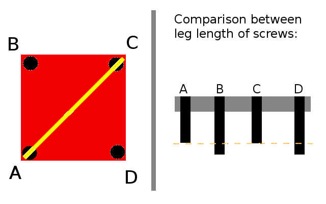
(N.b. The picture is not complete to enhance the point of what this guide tries to explain).
The picture above shows the heat bed in red and some black screws. The diagonal yellow line represents the wobble between A and C. You can confirm that the two corners have shorter legs by grabbing the Y-frame from below and gently tap the screw heads with your thumbs, alternating between A and C. Gently means no excessive force, but use high velocity - we need impact here. Listen for a special noise when tapping the screw heads. Compare with B and D. You will almost certainly here that the noise from A and C differ from B and D and voila -> you have found the wobble.
The diagonally wobble will always be found if there is a wobble present. A plane is defined by three points - so when you add a fourth point, that point has to just touch the plane. Now we just need to decide what to do next. You have of course two obvious options:
1. Heightening legs of A and C so they both touch the Y-fame.
2. Lowering legs of B and D, so A and C will both touch the Y-fame.
Both options are valid and depends on how you have measured the distances between the nozzle and the glass plate on several measure points. Notice that two legs are adjusted at the same time. You may also change just one leg if that is a better option for you. Remember to use the procedure of tapping the screw heads described above after every adjustment of a leg or legs. Alternate between A and C and B and D respectively to find the wobble. The wobble may change direction rapidly . I guess that you will be able to find a wobble as little as ~ 0.01 mm or in the neighbourhood of that.
Hopes this guide will help you out with the wobble - otherwise it may be in other components.
/Henrik
Re: Guide on calibrating the glass plate when corners wobble
Paolo's post below helped me out no end! I've printed a set out in PLA at 200um and they fit perfectly and what a difference they've made, the calibration is so much easier now! I'm finally able to print things out first go instead of needing several attempts because of the bed wobbling! This will keep me going until my MK2 upgrade kit arrives! Before these my bed would wobble badly diagonally and any attempt to get it level just caused the nozzle to too close/touching the bed in some corners and at the same time too far away in others!! I was at my wits end!
The link for them is http://www.thingiverse.com/thing:1530686
Hi Nigel,
Elastic bands are poor but effective method 😀
But thanks to the notice came from richard.I now i'm going to put on these:
Above all, thanks to Thingiverse...
Ciao