Concept ultralight Extruder assembly.
So I've been thinking about a simple system, that I have never seen on a 3D printer, and I would love to know why I haven't seen it? It just seems like the best option, yet I haven't seen it. It's not absolutely true to RepRap, as it would require a few additional pieces of metal hardware.
THEORY.
Mount the E motor directly in front of X motor, with shaft facing printer. Re-print Z parts to include a bearing that would mount a Keyed rod, going all the way across the front of the printer. (through the area the motor resides in) On this rod would be some kind of linear bearing (rotationally locked), that has a 3D printed worm gear wrapped around it, which will drive another small gear that will turn the extruder. The theory of this system, is to remove weight from the carriage, AND gear down.
Basically it removes MOST of the moving weight from the X axis. It would add weight to the printer overall, except it's on the Z axis, which is not "weight sensitive".
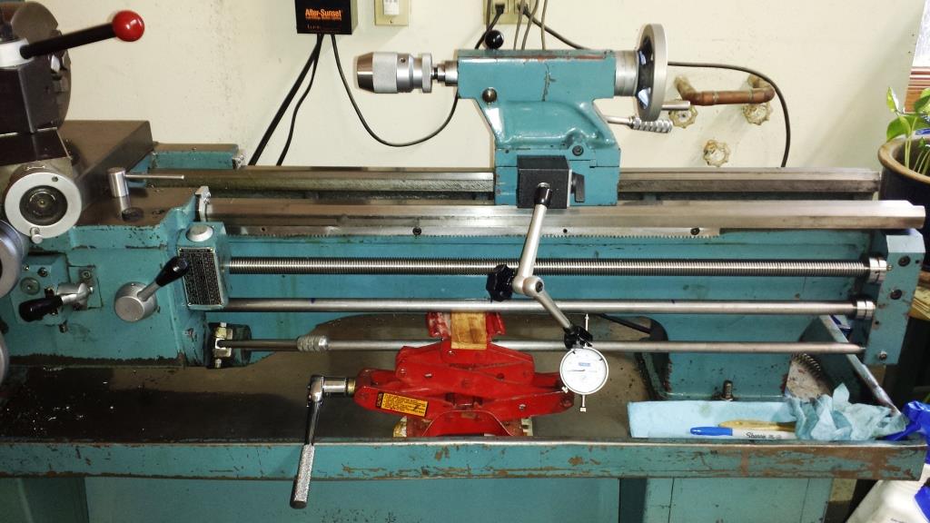
EDIT: This mechanism is called a "Feed rod" and the linear movement is done with the "Feed Rod Worm Gear", which appears to be a brass or bronze bushing. (On a traditional mechanical lathe)
Hi, I'm Sean. I used to work on CNC machines.
I try to not make mistakes, but the decision is YOURS.
Please feel free to donate to my filament/maintance fund.
Re: Concept ultralight Extruder assembly.
I guess it would be less precise.
Re: Concept ultralight Extruder assembly.
The cost to build this arrangement with the precision you need along with the need to have very accurate alignment to avoid issues on the x-axis would be exorbitant. In theory, it might work - but costly and I don't think the reduction of weight would ultimately be that much.
The feed rod, for a 3ft work area, metal lathe, is 75$ and the worm gear is 20$. (I just looked the prices up)
I highly doubt any 3D printer would need a nearly 1 inch rod that's almost 5 feet long. 😉
I'm sure if I look around long enough. (which I am now, I actually want to get this built!!! I think it will solve MANY issues, and allow CRAZY fast acceleration)
I'm now looking into seeing if I can find this style of rod for sale in smaller sizes, and then see if I can find a keyed bushing that could be used.
Hi, I'm Sean. I used to work on CNC machines.
I try to not make mistakes, but the decision is YOURS.
Please feel free to donate to my filament/maintance fund.
Re: Concept ultralight Extruder assembly.
Mount the E motor directly in front of X motor, with shaft facing printer. Re-print Z parts to include a bearing that would mount a Keyed rod, going all the way across the front of the printer. (through the area the motor resides in) On this rod would be some kind of linear bearing (rotationally locked), that has a 3D printed worm gear wrapped around it, which will drive another small gear that will turn the extruder. The theory of this system, is to remove weight from the carriage, AND gear down.
I think a better idea would be to use a flex cable to transfer the rotation of the E-motor (mounted out of the way) to the bondtech gears. You get even more weight savings and the precision is 1-to-1.
This concept was (at least, partially) explored in this thread.
Re: Concept ultralight Extruder assembly.
I think a better idea would be to use a flex cable to transfer the rotation of the E-motor (mounted out of the way) to the bondtech gears. You get even more weight savings and the precision is 1-to-1.
This concept was (at least, partially) explored in this thread.
That is a similar idea... I recall him mentioning he got it, but I don't recall exactly what he said about it... gotta ask that. lol.
I'm not a fan of flex cables, in *ANY* application. They are NOT accurate. (I mean, with 40:1, I guess it would be more accurate than I give it credit, but 40:1 is EXTREME gear reduction! Even for what I want!!!)
I'm just curious why I've never seen this concept. I know a small machine shop could PRODUCE (not design/setup) what I want (for their total cost) way under 30$/assembly, and it would be a HUGE improvement over *MOST* 3D printers on the market.
Hi, I'm Sean. I used to work on CNC machines.
I try to not make mistakes, but the decision is YOURS.
Please feel free to donate to my filament/maintance fund.
Re: Concept ultralight Extruder assembly.
Somehow I fail to visualize what you mean. Maybe it's because I don't all the words well enough 🙁
Could you add a drawing, no matter how crude?
I can't see how the extruder can move left/right.
As to reasons why this isn't used, my first thought would be that it uses a lot of transmissions - how much power (torque, I think?) is arriving at the extruding end?
How resistant is it, what would happen if there is a blockage?
The "feed Rod" is a smooth rod, with a "key" going down the length, there is then a "linear bushing" that also has a key groove in it, and it has a "worm gear".
The linear bushing with a worm gear, can slide linearly any distance with 0 rotation. When the Feed rod, turns, it will turn the worm gear, which in the application of a 3D printer, will turn the extruder.
The "Apron" as it's called on a lathe, rides on a dovetail, and (genrally) 3 rods on the front... AND a "rack" style gear down the length.
Through a MASSIVE number of gears, and and levers, you can do a LOT of things. (none of which are needed on a 3D printer)
On the 3D printer, you would maintain the 2 "normal" rods the Extruder carriage rides on, it would add a 3rd shaft, that would have the key on it, with the worm-gear bushing, with say, a 20:1 gear ratio to a standard spur gear, on the same shaft as the Bondtech gear.
The Extruder Carriage, would be able to have free range of motion from "end to end", with zero rotation on the extruder. If you rotate the "keyed shaft" the worm gear will drive the extruder, in either forward or reverse.
Example of keyed rod, without key.
[url- https://www.zoro.com/keyshaft-keyed-shaft-dia-8mm-500-mm-l-cs-8mm-gks-1045-500/i/G6917872/ ]8mm KEYED ROD[/url]
EDIT: Here is a video showing how an "Apron" works. The part that is of intrest is the "Worm Gear".
Regarding the concept of "lost power" would be nearly none. It would function on a SINGLE gear pair. (A Worm and a Spur).
If there's a blockage...
A) The bondtech gears would slip, and destroy the filament, causing a nasty jam. (Just like as if it was direct drive)
B) If the Worm/Spur gear was 3D printed, and under-spec in strength, it could in theory rip the teeth off. (which I would not think would be a large concern, as MANY older printers had 3D printed gears.
With the 20:1 gear reduction that a Worm gear produces, there would NEVER be any "relevant" load on the rod.
Hi, I'm Sean. I used to work on CNC machines.
I try to not make mistakes, but the decision is YOURS.
Please feel free to donate to my filament/maintance fund.