thanks for looking at the problem
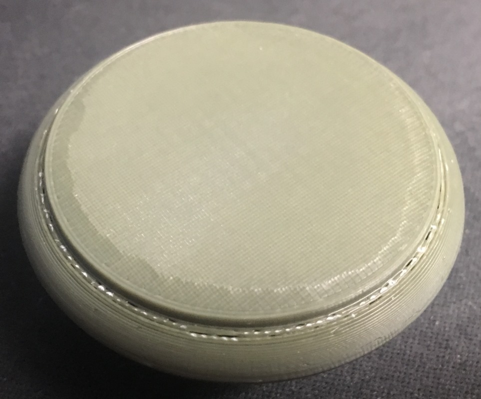
I just replied, got an internet error and lost the 1st response. That said so if it shows up, I'm not losing it and replying twice. Swiss and Dan thanks for your help. I did print the part using the project file you sent. Looks great. I've been gone most of the day so tomorrow I'll go over the project file in detail and will probably have more questions. I figured that the problem was self induced. I was going for a solid fill so if I sanded too much that I wouldn't go into the infill. I did have one, not posted, that had 50% infill and got the same bad result on the bottom curve. For completeness, I'm attaching a picture of the complete battery holder. The small cylinder is enclosed in wood and what shows it the larger cylinder and the sole that screws into it.
organizing data to understand what swiss did to get the print to work
I spent some time today doing side by side comparison between my .3mf file and the one that Swiss posted. Not much on the analysis phase but in capturing the screens the question that comes to mind is how did you get the layer heights for the modifiers in the right panel of the print tab? Attached is a pdf of side by side print screens of slicer with the file Swiss posted on the left and my original file I posted on the right.
?
I'm not clear on what your asking,
how did you get the layer heights for the modifiers in the right panel
do you mean how did I know what layers to apply the modifiers to? or how did I add them in the sidebar?
Also did you read through the Post that I left for Dan?
Regards
Swiss_Cheese
The Filament Whisperer
RE: ref question on ranges
I did read your reply and will go back through it now that I have a document showing what you did. That way your description will make more sense to me as I have to dig into the parameters you used for each modification. I used the wrong term. In the right panel of the print tab I see Range 0.00-0.75 mm, Range 1.00-2.50 mm, etc. My question goes more to process. How did you decide what to put in the range. Is there something in slicer to help or did you measure with calipers? Thanks for taking your time to help. My goal is to learn from this so I don't make the same mistake again.
Education is the name of the game
@jimd
How did you decide what to put in the range. Is there something in slicer to help or did you measure with calipers?
Ok, this is not a simple question, however the simple answer would be to say "experience", and yes there is something in slicer, and yes I do, and did also use calipers. (this would be so much easier if I was a guy that knew how to make videos)
starting at Layer 1, I printed your file, after making some changes to features that to me at least were obvious problems. In other words I left the file unchanged accept in the areas that I was 100% sure weren't going to work (print properly). This is a test print it gives you the clues to problems that the print may experience beyond your ability to see outright based on your experience. With experience you will have less and less issues in fewer test prints.
after printing the first version of your Part I had identified two issues. The main one was related to the fact that you were printing ABS and you weren't printing in an enclosure.
The part curled at the base.
The curling, In case it's not obvious, is around the two perimeter edge.
This is a cooling issue & would be a 3 page tutorial if I was to explain whats causing this, so sufficed to say that Adding 10 perimeters for the first solid layers 0.00- 0.75 helped with the material shrinkage since we weren't printing in an enclosure. I used calipers to measure this areas average and that's how I came up with 10 perimeters.
Hint: (you might also be able to use glue stick or Layerneer bed weld to help with this)
Next, Layers 1.50 - 2.50
This is the area where your overhang is, and it's quite the overhang at 90 degrees, we have to watch out here because if these layers fail the next several layers above them will fail as well, malforming the model, this would be best avoided, so In this case supports were added, using the method described in the previous post for Dan rogers. this "also" is an area where slicer is trying to add a bunch of solid layers/ infill. this is the default behavior of slicer, it views these steep areas as top or bottom surfaces, and if you have a certain amount of top and bottom layers specified, and a Minimum shell thickness specified, slicer is going to do all it can to meet that standard. Slicer is not wrong to do this, these settings get many a newcomer though prints that they had no idea wouldn't have worked otherwise. However as an experienced user we need to recognize that our prints are forming improperly, and change these defaults to get the result we desire. In your models case slicer was trying to added 5 layers of bottom fill in this height range and it was causing heat build up and adding to much plastic to this area in the form of 5 bottom layers with a minimum shell thickness of 0.7mm, per perceived bottom layer by slicer. so I turned off bottom layers for this area and added in a 3rd perimeter for strength, I could have gone 4 but less is more in this case.
Layers 7.50 - 9.40
I added 4 perimeters and removed top layers for the same reasons I describe in Layers 1.50 - 2.50, however top layers do not preform the same as bottom layers, so an extra 4th layer was added. (Your gained experience will show you why) (to much to explain here)
Layers 9.75 - 10.8
I choose to use a Concentric Top fill for the last outer layer in this range, and I choose it for looks. Many people do not understand how to apply Concentric Top fill, and so they complain that it is broken or doesn't work properly.
(know only that the number that I have added into the top Solid infill section in the modifier is one of two possible perfect multiples of the number of extrusion widths for this parameter)
Lastly, the Generic-Cylinder
This is a "Modifier Mesh" that I added to the center area of the model to #1 counteract the effects of some of the Height Range modifiers I added previously and #2 to adjust the amount of plastic being poured into the thread area.
The threaded area is thin, possibly to thin in my opinion, however I'm unfamiliar with the instrument you are eluding too, so what do I know? however to much plastic was being forced into this are by your settings just as layers 1.50 - 2.50 & 7.50 - 9.40 had. So I did the best I could in this area by reducing the "Perimeters" to 3 and the " Perimeter Extrusion width" to 0.38. The top and bottom fille were set back to defaults for the modifier and the top infill pattern was set back to Monotonic for this volume.
Additional basic settings:
layer height of 0.15 was selected to aid in the support of the steep overhangs while offering a reasonable height resolution. once the height resolution is selected you can scroll through the sliced layers with the slider on the sidebar and get the layer height information you need to effect and associated feature of the model in that range. ( your overhangs for example)
Ensure vertical shell thickness was turned off to aid in the controlled removal of excess plastic, also covered by the use of extra perimeters, in conjunction with proper infill amounts at 40%
I think cooling is self explanatory, you had auto cooling turned on, as a default this may be Ok, however for your models features you needed a steady constant cooling
I hope I was able to answer most of your questions, there is a lot to learn .
Good Luck
Swiss_Cheese
The Filament Whisperer
thanks for the detailed description of your thought process in approaching this problem
Thanks for sharing the details. I think I have enough information to do a detail study of the parameters you used so it will gel in my mind. Agreed the threads are thin but I already knew it would have a brass ring epoxied to the outside as shown in the attached photo. Soldering the wire from the spring contact inside to the brass ring was a challenge given the melting point of solder is a lot higher than ABS. I ended up inserting a bolt that matched the threads that served as a heat sink and mold if the plastic melted. They stayed intact.
Have you thought about conductive silver epoxy ?
MG Chemicals 8331D Silver Conductive Epoxy Adhesive
Regards
Swiss_Cheese
The Filament Whisperer
silver conductive epoxy
I didn't know it existed. I'll have a look. For my application I need the brass since it connects with a springy piece of metal in the upper battery housing, The process of inserting or removing batteries requires screwing/unscrewing which would wear down the cylinder as it rotates. I'll read up on the epoxy. It might be good in place of a wire for a static connection. Thanks for your help.
Have you thought about conductive silver epoxy ?
MG Chemicals 8331D Silver Conductive Epoxy Adhesive
Regards
Swiss_Cheese
Thank you. Bookmarked.
I can envision this coming in handy for various projects, low-current, of course.
Silver is the best conductor of electricity
@jsw
It's better then you might be thinking, I use it on PCB's all the time and it's very low resistance.
good stuff
Swiss_Cheese
P.s. that's why it cost so much.
The Filament Whisperer
Great Thread
This is a great thread - save for future needs.
--------------------
Chuck H
3D Printer Review Blog
RE: Very poor print quality on underside of ABS even with supports
I've used the .3mf file that you sent to successfully print several new sole pieces. I've decided to make a change to add a recess in the bottom to allow me to insert a machined wood disk that I can engrave. For that I'll need to send a part from Fusion 360 to Prusa Slicer. Since most of the new design is the same as the original one is there a way save your modifications (see attached photo) for the part so I don't have to recreate all these settings from scratch. Attached is a file showing what I would like to save and a screen shot of the modification I made to the bottom of the sole. Thanks.
RE: Very poor print quality on underside of ABS even with supports
Because of all of the modifiers that swiss_cheese helped me with to get the original part to print correctly it took me a while to get the the new part (with recess in bottom) printing correctly. I added a new modifer which is a cylinder support enforcer. It is set to the size of the recess. Worked great. The supports came off cleanly. Attached is the new project file. The second cylinder object is the one I added.
RE: Very poor print quality on underside of ABS even with supports
file didn't append. trying again.
RE: Very poor print quality on underside of ABS even with supports
@jimd
Sorry the file didn't append, you do nice work, I'll bet it turned out great. if you feel like trying to get the file to append I'll take a look, even some images might be nice.
Regards
Swiss_Cheese
The Filament Whisperer
RE: Very poor print quality on underside of ABS even with supports
I just remembered that I have to zip the project file so I can attach it. See my post of 10/01/2022 at 9:10 pm for the explanation.