Some corners of the layers are lifted (in PETG)
Hello! this is my first post here in the forum since I've been a Prusa user for a couple of weeks and although I've had some little thing, I've solved it either by reading here or by watching videos on youtube, but this problem is beyond me. Let me explain:
In monolithic parts does not happen, in fact it is happening now that I am printing a fender for my scooter and it is a complicated piece. The thing is that I don't know if it's because of the PETG shrinkage or what, but when printing in some corners with some overhang (but totally printable) the layer folds upwards when drying, and this ends up overlapping layer after layer until it ends up either by jumping that piece from the bed or by stopping the printer by shock. I have to say that for this piece it has no infill, it is all contours. The curious thing is that I have noticed that this happens almost every time in the parts / faces that look to the rear, giving less in the front, I do not know if it is something related to the ventilation of the layer, if I have to turn on the fan at 100%. It is also true that in cases not very beastly, when the piece ends up having more extension is solved, although the finish in that area is pitiful. If you know how I could solve that I would appreciate it, because with the mudguard I had to repeat twice the print and the last one pausing and with the pliers that come in the prusa, lower (yes I know, a very nasty trick) that part still half hot to try to level it, but of course, this because I was working in the same room, but I do not want to think about having to be on top of every "weird" print because this happens.
Here are two photos that I hope are descriptive enough ....
Best regards!
Translated with www.DeepL.com/Translator (free version)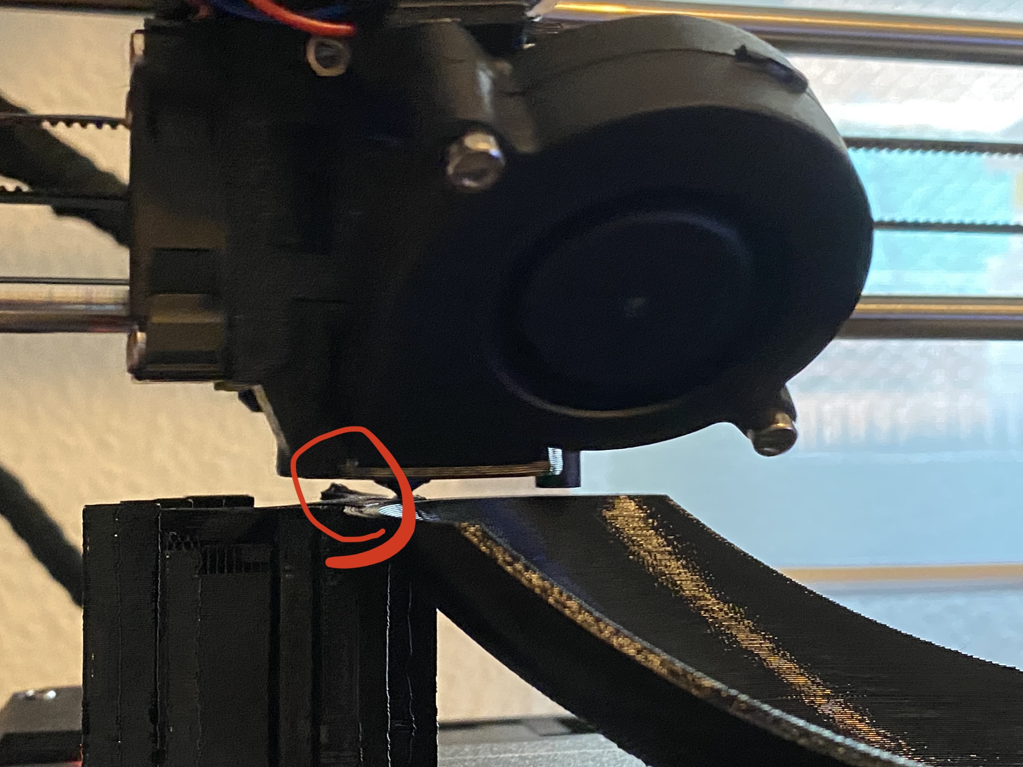
Zip it and upload it
Sounds like you may be experiencing warping - hard to say from the picture. once you have sliced your model, save the prusa slicer project as a .3mf file, upload it here. that will reveal more.
Possible warping or poor bed adhesion
[...] The thing is that I don't know if it's because of the PETG shrinkage or what, but when printing in some corners with some overhang (but totally printable) the layer folds upwards when drying, and this ends up overlapping layer after layer until it ends up either by jumping that piece from the bed or by stopping the printer by shock.
It sounds like you're getting some warping. This can be due to weak bed adhesion, or simply uneven cooling of the part as it prints. Look at the underside and see if you can detect any lifting of the part off the bed in those areas where it is warping. If so, give your bed a good clean. A brim can help, or "mouse ears" can be created to help hold the print in place.
[...] The curious thing is that I have noticed that this happens almost every time in the parts / faces that look to the rear, giving less in the front, I do not know if it is something related to the ventilation of the layer, if I have to turn on the fan at 100%.
PETG normally prints with little (30%) to no cooling, but it can help in some cases, particularly if you have severe overhangs.
As @dan-rogers notes, it is much easier to help if we can see your part & settings. Save your current 3MF project file, zip it up, and attach it to a reply here so we can see your part & settings and give better recommendations.
😎
It doesn't look to me like your suffering from warping. based on what I can tell from the image you posted it looks like you have a glob of PETG that deposited on you support structure, this could be due to over extrusion, which can be caused by several things, it could be caused by selecting layer heights that are to low etc,,. As mentioned by others the easiest way to diagnose the problem for us, the community, is if you post a .3mf project file with the settings you have been using so you can see them relative to the model your trying to print. the .3mf file must be zipped up in order for you to post it here on the Prusa forums.
Good Luck
Swisss_Cheese
The Filament Whisperer
Maybe solved?
Well i "think" i found the answer. The piece hasn't infill, only perimeters and i repeated with 3 perimeters and 100% infill and the warping almost dissapeared.. not everything but A LOT better now... but i have to say... putting supports makes the piece looks HORRIBLE
extrusion
Well i "think" i found the answer. The piece hasn't infill, only perimeters and i repeated with 3 perimeters and 100% infill and the warping almost dissapeared.. not everything but A LOT better now... but i have to say... putting supports makes the piece looks HORRIBLE
Lower the infill to like 20-30% and see what happens. Post a pick. You might have an extrusion issue also.
--------------------
Chuck H
3D Printer Review Blog
Consider wider perimeters
Well i "think" i found the answer. The piece hasn't infill, only perimeters and i repeated with 3 perimeters and 100% infill and the warping almost dissapeared.. not everything but A LOT better now... but i have to say... putting supports makes the piece looks HORRIBLE
No guarantees, but you can also experiment with wider extrusions. With quality nozzles, you can use perimeter extrusion widths up to approx. 200% of your nozzle size, so a 0.7-0.8mm width might work. This reduces fine details but can be fine for large functional parts. It also adds strength and speeds up print times if you're able to avoid printing a perimeter or two. If you're doing larger parts, a larger nozzle can really help with these sorts of issues.
Again, save your current 3MF project file, zip it up, and attach it to a reply here so we can see your part & settings and give better recommendations. It's hard to visualize exactly what's going on with the picture you provided.
Glad you got the worst of the warping figure out. It's always a balancing game.
RE: Here's the 3MF
No guarantees, but you can also experiment with wider extrusions. With quality nozzles, you can use perimeter extrusion widths up to approx. 200% of your nozzle size, so a 0.7-0.8mm width might work. This reduces fine details but can be fine for large functional parts. It also adds strength and speeds up print times if you're able to avoid printing a perimeter or two. If you're doing larger parts, a larger nozzle can really help with these sorts of issues.
im not an advanced user to try those kind of things... but i will investigate about that.
Lower the infill to like 20-30% and see what happens. Post a pick. You might have an extrusion issue also.
I did a lot more pieces without any issue. I want 100% infill to make it hard to break (is a scooter fender).
Again, save your current 3MF project file, zip it up, and attach it to a reply here so we can see your part & settings and give better recommendations. It's hard to visualize exactly what's going on with the picture you provided.
Here is the 3MF file.
Perimeter widths and count for strength
im not an advanced user to try those kind of things... but i will investigate about that.
It's not particularly tricky to do. Just go into Print Settings->Advanced->Extrusion width and try increasing Perimeters and External perimeters up to 200% of nozzle size (ideally a bit lower). Try 0.7 with a 0.4mm nozzle for example. I've got some notes here that might be helpful.
I did a lot more pieces without any issue. I want 100% infill to make it hard to break (is a scooter fender).
100% infill won't add as much strength as an additional (wide) perimeter or 2. Stefan did an excellent video on this over on his CNC Kitchen YouTube channel.
Here is the 3MF file.
You need to put any file attachments in a .zip archive to upload them here.
The zip
im not an advanced user to try those kind of things... but i will investigate about that.
It's not particularly tricky to do. Just go into Print Settings->Advanced->Extrusion width and try increasing Perimeters and External perimeters up to 200% of nozzle size (ideally a bit lower). Try 0.7 with a 0.4mm nozzle for example. I've got some notes here that might be helpful.
I did a lot more pieces without any issue. I want 100% infill to make it hard to break (is a scooter fender).
100% infill won't add as much strength as an additional (wide) perimeter or 2. Stefan did an excellent video on this over on his CNC Kitchen YouTube channel.
Here is the 3MF file.
You need to put any file attachments in a .zip archive to upload them here.
i did! but it didn't attached. try again!
your post
It's not particularly tricky to do. Just go into Print Settings->Advanced->Extrusion width and try increasing Perimeters and External perimeters up to 200% of nozzle size (ideally a bit lower). Try 0.7 with a 0.4mm nozzle for example. I've got some notes here that might be helpful.
uhmmm checking your post.. veeeery interesting 🙂
Wider extrusions and more perimeters will add strength and speed up print times
i did! but it didn't attached. try again!
Attachment removed
More about this
These areas are where the warping came strongly:
This is the first picture of this thread:
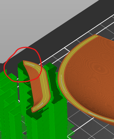
Another strong warpings:
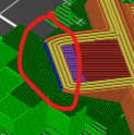
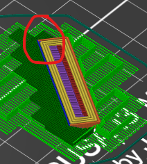
only is those circled parts. Another ones are perfect.
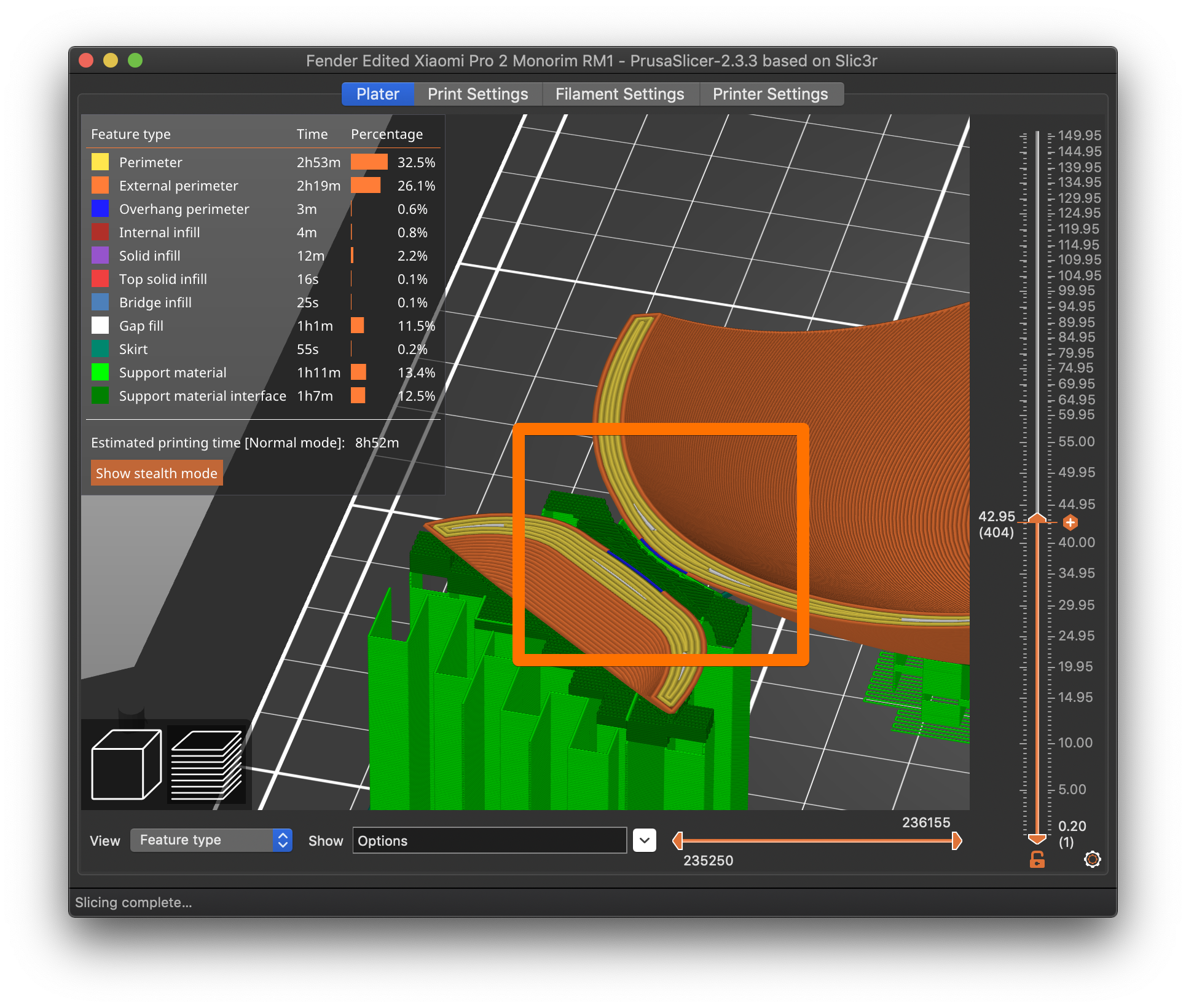
Now the results:
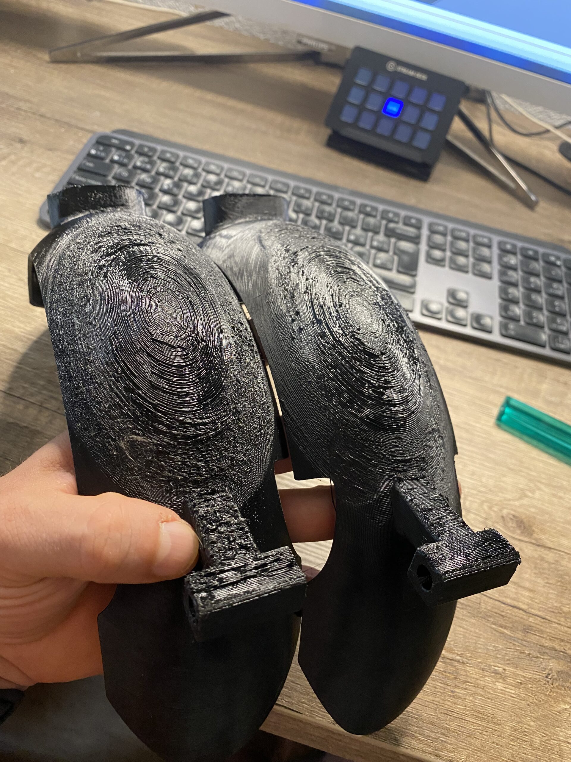
Left one only perimeters (lot worse look and a lot of warping)
Right one with 3 perimeters and 100% infill (look a bit better and less warping.. but a lot of threads making everything sooo dirty.
Both of them with a difficult sanding solution. The more vertical zones are made perfect.
Invert
If it were me I would try to invert the part. This way the visible part is going to be smooth and the part in contact with supports is not. Though if I was looking for super smooth I’d be looking at soluble supports