RE: need advice for optimizing prints
@tim-m30
I would print these with zero infill - and cut some holes through them.
If you subtract a narrow slice through the inside of your model, say aligned with the roof ridge but never quite breaking theough the surface at any point, the slicer will surround the void with a perimeter - just where you need a custom support. You can place extra supports wherever needed by cutting more slices.
And to smooth the roof add another surface layer or two.
RE: need advice for optimizing prints
Here's an OpenSCAD script to illustrate the method:
// Demo building

// set to 0 for stl/3mf production, set to 1 to see internal structure
showconstruction=1;


section=[[0,0],[0,30],[25,40],[50,30],[50,0]];
reinforce=[[1,1],[1,29],[24,39],[49,29],[49,1]];

difference(){
  rotate([90,0,0]){
    linear_extrude(height=240)
      polygon(section);
  }
  for(step=[1:11]){
     translate([0,-step*20,0]){
       rotate([90,0,0]){
         linear_extrude(height=1)
           polygon(reinforce);
        }
      }
    }
    // Just for illustration
    if(showconstruction){
      translate([0,-240,20]){
        cube([25,240,25]);
      }
    }
  }
Change the value of showconstruction before printing.
Cheerio,
RE: need advice for optimizing prints
I probably made my examples too thin Tim, there’s just perimeters. If they were adjusted to be thicker so they had infill they should slice normally.
Those roofs should print without support and internally once made thicker it wouldn’t matter if the internal slope wasn’t perfect as it would be inside the house model and not visible at all.
As a matter of interest where abouts were those slicing artefacts Tim, if like to see what it’s doing.
RE: need advice for optimizing prints
@neophyl
I was nit-picking. Look at layer 80 in your 3mf, there are gap fill voids in the wall perimeters in the center building. And when I applied my 0.2 mm layer profile with PLA - things really broke: actual holes in walls, a wall that went from one to two perimeters mid length, with seams in strange places.
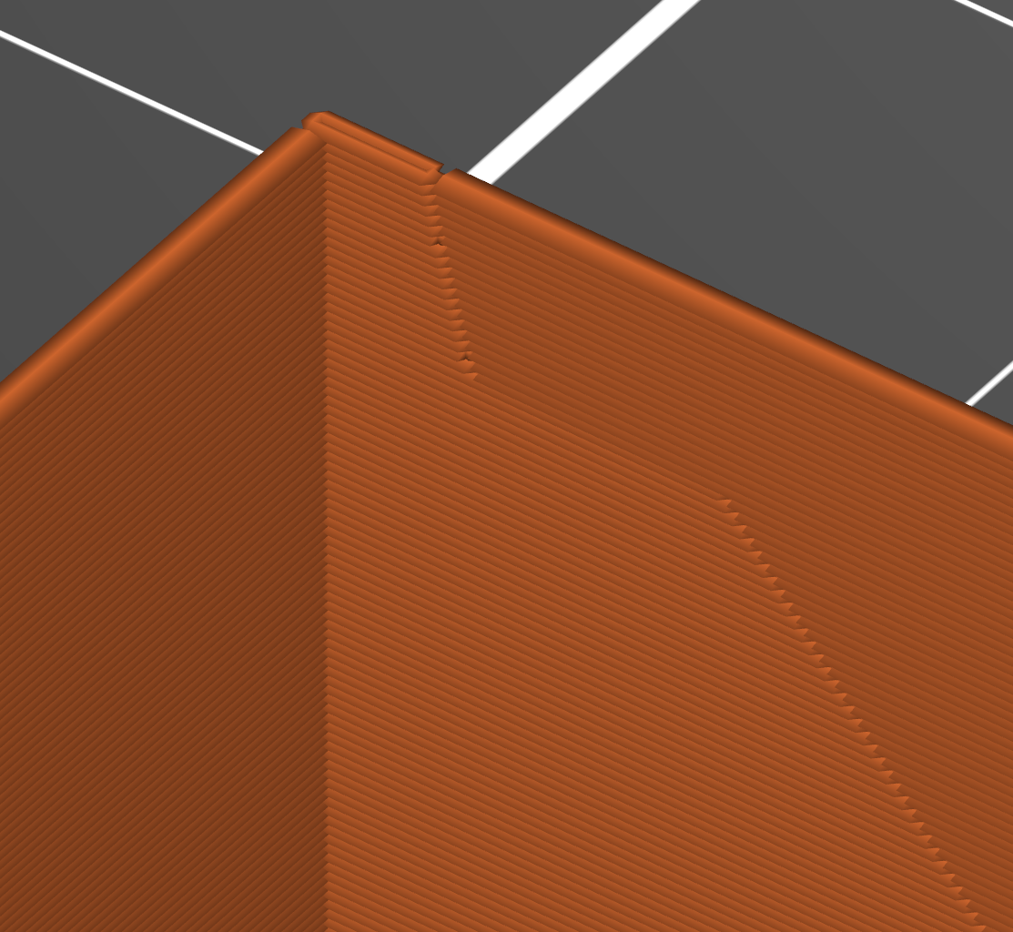
I may have run into a bug in 2.3.0a2 ... I can't get the odd features back. But this clip shows one of the places the oddities were seen: a corner with one perimeter, a corner seam, then two, then midwall a seam and back to one. In other spots in that slice, there were long voids in the perimeters at seams, a typical thin wall occurrence.
RE: need advice for optimizing prints
@tim-m30
Weird thing when I opened my 3mf on the work pc in 2.2 it set the printer to an Ender 3 and when I opened it in PS2.3 it set it to a Mini. The project was saved on my home pc using a MK3 based profile so not sure why that happened - hey ho.
Both PS 2.2 abd PS2.3 do seem to be doing the gapfill voids on that centre building for some reason. However with the print profile it doesnt show any slice changes like in your picture. Those changes do seem to correspond to the positions where the gapfil stop though so yeah I'd agree there's some thin wall weirdness going on with whatever profile you used.
I think I will make them thicker and add in a partial floor to glue them down when I get home. Should only add an extra step in the Blender workflow to get a lip around the bottom.
That should also remove the gapfill issue but will then probably suffer from the solid infill on sloping perimeters bug that hasnt been fixed yet ( https://github.com/prusa3d/PrusaSlicer/issues/223 ).
RE: need advice for optimizing prints
Hi @neophyl
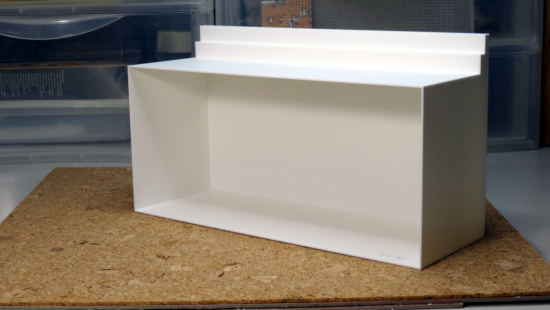
I wanted to share the result of printing one of the 3 modified models you sent me yesterday.
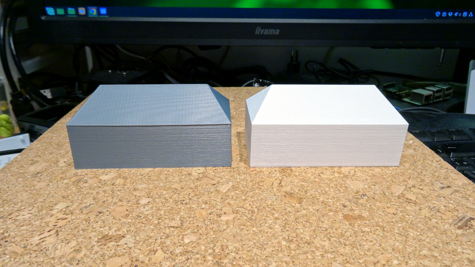
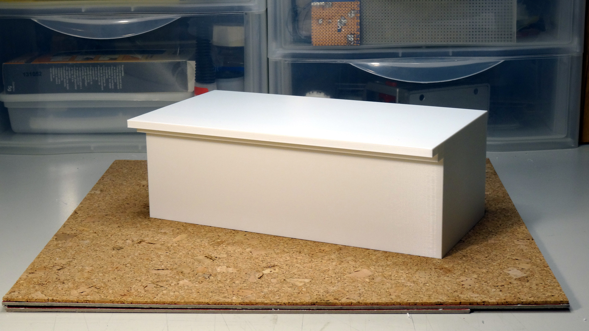
The grey one is the hollowed version, the white one is filled with gyroïd (5% in the body and 15% in the roof).
To be honest, based on the experiments I did after building the printer, I was not very confident. The same roof had small protuberances here and there on the most horizontal pans with a 5% infill. They disappear entirely with 15%, hence my current settings. So I could not imagine that it would work this way with 0% infill. Maybe the defects were caused by the junctions between the infill pattern and the perimeter. Or it was not related to infill at all, but having made several tests in different configurations to check if the X/Y axis would be involved, I came to this conclusion. I have no explanation at this time and am very interested in possible ones.
The only defect that can be seen is a slight lip on parts of the edges between the walls and the roof. One can notice the dropped shadow it creates. However, this is not terrible, since a light sanding should quickly fix it.
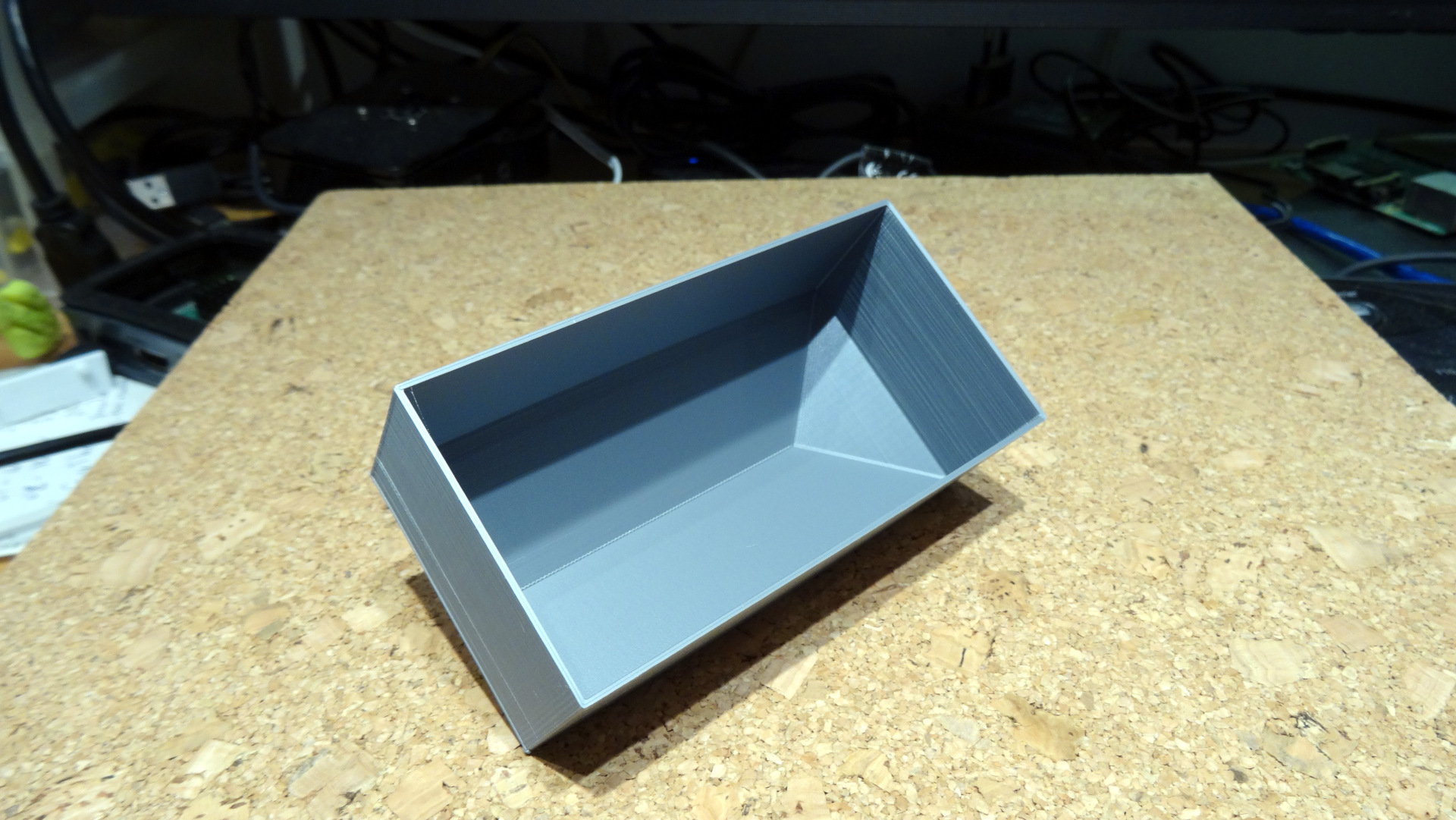
I have been stunned by the quality of the underneath faces too. Although it has no importance since they are not visible, it's amazing to notice that they are as perfect as the upper ones, although printed almost in the air.
The walls are a bit flexible when pressed but making them a bit thicker should solve this. I just need to add a base face for being able to attach the buildings to the terrain with double-face adhesive tape, and it will be perfect.
One last question: some of the buildings are multi-stories ones. Would some kind of internal vertical walls here and there (every 5 cm for instance to form a kind of very low percent infill) be necessary to avoid squashing the building while manipulating it or making the walls thicker would be sufficient? PLA seems strong enough under normal conditions, but it's unlikely I'll be the guy who will assemble the global model.
I would not thank you enough for the assistance you brought me and the knowledge step it let me do.
Best regards.
MK3S, OpenSCAD, Blender, SolveSpace, Linux, electronics, robotics, software
RE: need advice for optimizing prints
I agree its pretty amazing what our printers can do, especially if you design with the limitations in mind. I've printed parts with more extreme overhangs in the past and they worked well. I was mildly concerned the interior wouldn't look as good but considering that is a non visual area I didn't think it would matter for your use anyway.
PLA is a very good material in its place. Its strong and prints easily/well. Its major shortcoming is its low heat resistance but where that's not going to be a factor its usually a good choice.
I would think that just making the walls a bit thicker would help but as that will then start using infill it might raise other issues. Unfortunately its one of those print a test one and see situations really. Making them thicker and also adding an extra perimeter to take up the extra space should also be considered instead of letting it use infill.
You can add a partial floor very easily by adding a step to the Blender workflow and I think if the thickness was increased it will probably sort out the other issues.
Would you have one of the multi-storey ones you could share ? Basically the worse case one 🙂 Slicer has a known issue with transitions between perimeters that have gapfill or change to layers of solid infill such as inside walls. The threads are titled with terms like 'Buldge at xx' or similar which you can find on the forum if you want to do some research, so if you can avoid that it would be best.
Phil
RE: need advice for optimizing prints
In the meantime, I've played with the OpenSCAD code provided by @diem (thank you for this example). It happens that I know OpenSCAD a bit (not heavily used, but I did some complex stuff with it in the past).
Being more a keyboard guy than a mouse addict (I'm a coder) and considering the simplicity of most of the building's geometry and the fact that, dimensions apart, a lot of them share the same structure, I think that I'll switch to this option. Its parametric nature will make the process quite efficient. I've already coded a module for a basic 2 pans roof building, that can be parametrized bit its footprint dimensions, its height, and the roof apex above the last storey. Several instances can then be assembled to create L or T-shaped ones thanks to boolean operators. BTW OpenSCAD is very good at CSG and does not create the internal hidden vertices, edges and facets the graphics-oriented tools tend to produce and that must be removed by hand as you explained.
OpenSCAD can quickly become slow as a snail when you use complex curved surfaces, but since we only have boxes and prims here, it generates the STL almost instantaneously.
I'm probably going to give a refresher to my OpenSCAD former knowledge since I've found a new playground here for exploiting it 😉
MK3S, OpenSCAD, Blender, SolveSpace, Linux, electronics, robotics, software
RE: need advice for optimizing prints
Unless you are careful openscad has been known to generate models that slicer has problems with. Even relatively simple ones.
RE: need advice for optimizing prints
Unless you are careful openscad has been known to generate models that slicer has problems with. Even relatively simple ones.
Argh... Good to know. No solution seems to be ideal then 🤨
I've explored a bit this direction these last hours, and for the moment hadn't problems with the slicer. I've more problems trying to reconnect my brain to OpenSCAD 😊. Maybe I'll be lucky enough not to be blocked since after all my models are quite simple from the geometrical point of view.
MK3S, OpenSCAD, Blender, SolveSpace, Linux, electronics, robotics, software
RE: need advice for optimizing prints
@tim-m30
Weird thing when I opened my 3mf on the work pc in 2.2 it set the printer to an Ender 3 and when I opened it in PS2.3 it set it to a Mini. The project was saved on my home pc using a MK3 based profile so not sure why that happened - hey ho.
I'm think bump-in-the-night defect in Plicer. I thought it was alpha issues - could have been something off in teh Blender mods you made, breaking the models in ways Plicer had issues with. I certain saw weird things. Why I can't recreate them is another mystery. I wasn't doing anything weird except playing with modifiers to add infill at the roof line.
RE: need advice for optimizing prints
@eric-g-pascual
Adding a single layer for Layer 1 will strengthen the walls considerably. Making it thicker - for your application - sounds like wasting print time and material. If you use something like LINE infill at 5% your print times drop considerably with very little change in surface quality. Rectilinear can work too, but you need to tweak infill flow upwards to make it work well - has to do with Rectilinear having only one extrusion every other layer, so you can get a type of under-extrusion: I set infill extrusion width above 0.6 mm, which works well.
RE: need advice for optimizing prints
Adding a single layer for Layer 1
Hi Tim,
I'm not sure tu understand what you mean by this. Could you elaborate please?
MK3S, OpenSCAD, Blender, SolveSpace, Linux, electronics, robotics, software
RE: need advice for optimizing prints
@eric-g-pascual
Just for structural strength - you won't need five bottom layers to allow tape to hold the parts down. A single bottom layer should be enough for the normal thickness double-sided sticky tape (the non-foam variety). That one layer will also help hold the wall true.
Easy to test, try printing with one, two or five bottom layers. Judge which is best.
And - if it wasn't clear in my earlier posts, I placed the models on the bed, merged them in slicer, then added a top modifier box to envelope the roofs, and set infill to 5% Line type. At 2 perimeters with 0.20 layers, the houses and roofs printed fairly well - and all I had to do was scale them to print size within Slicer - no external app needed.
RE: need advice for optimizing prints
@tim-m30
Thanks. I understand better now.
I was using the box modifiers too for setting different infills for the body and the roofs for printing STL produced by Sketchup (which are solid models by default).
The latest printed models were hollow one, which STL has been generated by OpenSCAD. I've been using OpenSCAD a long time ago for not 3D-printing related activities but was not aware it can produce STL too. It works pretty well (I'm used to coding 😊 ) and a fully hollow model of a large warehouse (200x100x70) completed fine within 8 1/2 hours with a great finish. I've set the wall thickness to 1mm because they are quite wide and I was afraid they could be deformed if thinner. Even the longest ones are perfectly straight.
I need to print a base plate now for attaching the body to the terrain and ensuring no deformation could happen. It will have a minimal structure (mainly a frame with a central median reinforcer, all of them about 1.5cm wide to match the adhesive tape dimension).
However, simulating various scenarios, I've been surprised by the fact that hollowing does not reduce the print time as much as I was expecting. I suspect that since the infill is printed with high speed (and linear ones are the fastest of course) its additional printing time is compensated by the fact that there are no additional external perimeters on the inside faces of the walls in the case of infill solids. These perimeters being printed with a slower speed, they take a significant amount of time. Anyways the filament consumption is quite higher as expected when using infills. However, when adding the cost of the base plate (which needs to be thicker when done as a separate part as it would have been as a shell layer), the final balance is not so much positive.
It's not obvious to choose the right strategy, especially when models are massive one-of-a-kind ones and you thus can't try different options (unless you're OK with sacrificing filament and hours of print for the sake of science 😀).
MK3S, OpenSCAD, Blender, SolveSpace, Linux, electronics, robotics, software